Mouser.ee
Adafruit NeoPixel Überguide
Created by Phil ip Burgess
Last updated on 2014-12-02 12:45:12 PM EST
Adafruit Industries
The Magic of NeoPixelsIncorporating scads of LEDs into an electronic project used to be a hairy prospect, averitable rat's nest of wires and code. The arrival of dedicated LED driver chips broughtwelcome relief, offloading grunt work from the microcontrol er and al owing one to focus onthe application. Much simpler, but stil not "Christmas light" simple.
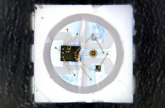
The WS2812 Integrated Light Source — or NeoPixel in Adafruit parlance — is the latest
advance in the quest for a simple, scalable and affordable ful -color LED. Red, green and
blue LEDs are integrated alongside a driver chip into a tiny surface-mount package
control ed through a single wire. They can be used individual y, chained into longer strings or
assembled into stil more interesting form-factors.
We know you're eager to get started…but If this is your first time using NeoPixels,please at least read the "Best Practices" page before connecting anything!
Important Things to Know About NeoPixels in General
Not al addressable LEDs are NeoPixels. "NeoPixel" is Adafruit's brand for individual y-addressable RGB color pixels and strips based on the WS2812 and WS2811LED/drivers, using a single-wire control protocol. Other LED products we carry —WS2801 pixels, LPD8806 and "analog" strips — use different methodologies (and have
Adafruit Industries
their own tutorials). When seeking technical support in the forums, a solution can befound more quickly if the correct LED type is mentioned.
NeoPixels don't just light up on their own; they require a microcontrol er (such asArduino) and some programming. We provide some sample code to get you started.
To create your own effects and animation, you'l need some programming practice. Ifthis is a new experience, work through some of the beginning Arduino tutorials to get afeel for the language.
NeoPixels aren't the answer for every project. The control signal has very strict timingrequirements, and some development boards (such as Netduino or Raspberry Pi) can'treliably achieve this. This is why we continue to offer other LED types; some are moreadaptable to certain situations.
Can I use NeoPixels for POV (persistence of vision) displays?
Not recommended. The refresh rate is relatively low (about 400 Hz), and color displays infast motion may appear "speckled." They look fine in stationary displays though (signs,decorations, jewelry, etc.). For POV use, (http://adafru.it/306) wil lookmuch better (they have about a 4 KHz refresh rate).
How about for light painting?
Definitely! The slower movement used for photographic light painting doesn't calattention to the limited refresh rate; the results look great, especial y with a light diffuser.
Adafruit NeoPixels are Available in the Following Products:
Adafruit Industries
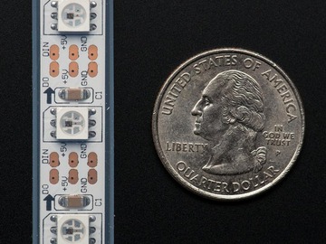
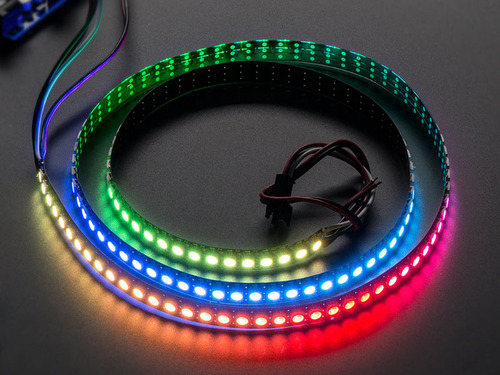
NeoPixel Digital RGB LED Weatherproof
Strip is available in three different "densities":
30, 60 and 144 LEDs per meter, on a white or
black backing strip.
The approximate peak power use (al LEDs onat maximum brightness) per meter is:
30 LEDs: 9.5 Watts (just under 2 Amps at
5 Volts).
60 LEDs: 18 Watts (about 3.6 Amps at 5
Volts).
144 LEDs : 35 watts (7 Amps at 5 Volts).
Mixed colors and lower brightness settings wiluse proportional y less power.
Adafruit Industries

The product list continues below. But first…
Important Things to Know About NeoPixel Strips
NeoPixel strips are sold in one meter lengths. The 144 pixels/meter strips are alwaysseparate 1-meter lengths. For 60 and 30 pixels/meter strips, orders for multiplemeters wil be a single contiguous strip, up to a limit: 4 meters for 60 pixels/meterstrip, or 5 meters for 30 pixels/meter strip.
Adafruit Industries
For 60 and 30 pixels/meter strips, if purchasing less than a ful reel (4 or 5 meters,respectively), the strip may or may not have a 3-pin JST plug soldered to one end.
These plugs are for factory testing and might be at either end — the plug does notalways indicate the input end! Arrows printed on the strip show the actual datadirection.
Although these strips are flexible, they do not tolerate continuous and repeatedbending. A typical application is architectural instal ations, where they can be curvedaround columns and then stay put. Repeated flexing (as on costumes) wil soon crackthe solder connections. For wearable use, either affix shorter segments to a semi-rigidbase (e.g. a hat, BMX armor, etc.), or use the individual sewable NeoPixels shown later.
The flex strips are enclosed in a weatherproof silicone sleeve, making them immuneto rain and splashes, but are not recommended for continuous submersion. Early 144pixel/meter strips were not weatherproof, but the latest batches now include thisfeature.
The silicone sleeve can be cut and removed for a slimmer profile, but the strip is nolonger weatherproof.
Very few glues wil adhere to the weatherproof silicone sleeve. Using zip ties for a"mechanical" bond is usual y faster and easier. The only two reliable glues we'vefound are Permatex 66B Clear RTV Silicone (not al silicone glues wil work!) and LoctitePlastics Bonding System, a 2-part cyanoacrylate glue. The Permatex 66B silicone canalso be used to seal the open end of a cut strip.
Al strips are manufactured in 1/2 meter segments that are then joined into a longerstrip. The pixel spacing across these joins is 2-3 mil imeters different than the rest.
Some batches of 144 pixel strip don't havepads between the LEDs. If you cut these intoshorter sections, the only way to connect tothem (except at the half-meter segments) is tocareful y solder directly to the LED. The cornerwith the notch is the GND pin.
Adafruit Industries
NeoPixel Shapes: Rings, Matrix, Shield
and Strip
These ready-made shapes simplify manyprojects! Rings are perfect for jewelry,timepieces and navigation displays. Matriceswork for bitmap displays and scrol ing messagesigns.
Al NeoPixel shapes can be chained (the outputof one can connect to the input of the next) andare control ed from a single microcontrol er pin.
adafru.it/1643) — 1.5
inch (37 mm) outside diameter. Max 5V @
750 mA.
adafru.it/1463) — 1.75
inch (44.5 mm) outside diameter. Max 5V
@ 1A.
adafru.it/1586) — 2.6
inch (66 mm) outside diameter. Max 5V @
1.4A
(http://adafru.it/1487) —
64 LEDs total. The pixel spacing and
board size al ow seamless tiling. Max 5V
@ 4A.
fru.it/1430) —
5x8 matrix plugs directly atop an Arduino
board (can also be tiled separately if
desired). If the overal brightness is
careful y limited, can be directly powered
from the Arduino. For most situations,
connecting an external power supply is
recommended. Max 5V @ 2.4A (the
Arduino can only supply about 500
mil iamps).
p://adafru.it/1426) — 8
NeoPixel LEDs on a rigid circuit board
packed even more tightly than the flex
strips. Solder pads on the back for
Adafruit Industries
connecting wires or breadboard pins (notincluded).
Current ratings shown are approximatemaximums (al pixels on at peak brightness).
Mixed colors and lower brightness settings wiluse proportional y less power.
Important Things to Know About NeoPixel Rings
When soldering wires to these rings, you need to be extra vigilant about solder blobsand short circuits. The spacing between components is very tight!If using al igator clips, we recommend first soldering short jumper wires to the ringinputs and connecting the clips to those, for similar reasons. (Some of our tutorialsand product photos do show alligator clips directly connected to the rings, but
Adafruit Industries
we've had a lot of experience using them.)
Adafruit Industries
Single NeoPixels al ow maximum control
over individual pixel placement (some are even
sewable!), while bulk sheets are a more
economical option.
it/1260)
— designed specifical y for wearables
and "soft circuits," these NeoPixels can
soldering works too). Sold in packs of 4.
12) —
accommodates pin headers with
standard 0.1" spacing. Sold in packs of 4
(headers are sold separately).
afru.it/1612) — the
smal est NeoPixel breakout boards have
solder pads on the back. Sold in packs of
5.
34) —
provides NeoPixels in a more traditional
LED form-factor.
)
— bare NeoPixels for advanced users
wanting to design their own custom
boards and shapes. 10 pack. This is a
surface-mount device, not
recommended for novice soldering. For
.
it/1378) —
contains the NeoPixel control er circuit
without the actual LEDs (can be added
separately). 10 pack.
Adafruit Industries
Flora RGB Smart NeoPixel
(Version 1) — Discontinued, but
listed here for compatibility info. This
earlier version of our Flora NeoPixel is
identified by a smal driver chip on the
back side. V1 pixels were original y
programmed using the Adafruit_FloraPixel
library. Al new code should instead use
/aZU), which
handles either type.
Al individual NeoPixels can be chained from asingle microcontrol er pin, with the one caveatthat WS2812 and WS2811 (e.g. Flora V2 andV1) types can't be mixed in a single chain.
Each individual NeoPixel requires 60 mil iampsmax at ful brightness. Mixed colors and lowerbrightness settings wil use proportional y lesspower.
Adafruit Industries
Best Practices
Improper use can damage your NeoPixels. Before
diving in, be aware of the following:
Before connecting NeoPixels to any power source, add a large capacitor (1000 µF,
6.3V or higher) across the + and – terminals as shown above.
Place a 300 to 500 Ohm resistor between the Arduino data output pin and the
input to the first NeoPixel. This resistor must be at the NeoPixel end of the wire to be
effective! Some products already incorporate this resistor…if you're not sure, add
one…there's no harm in doubling up!
Try to minimize the distance between the Arduino and first pixel.
Avoid connecting NeoPixels to a live circuit. If you simply must, always
connect ground first, then +5V, then data. Disconnect in the reverse order.
If powering the pixels with a separate supply, apply power to the pixels before
applying power to the microcontrol er.
Observe the same precautions as you would for any static-sensitive part; ground
yourself before handling, etc.
NeoPixels powered by 5v require a 5V data signal. If using a 3.3V microcontrol er you
must use a logic level shifter such as a (http://adafru.it/e5g) or
(http://adafru.it/1779). (If you are powering your NeoPixels with 3.7v like
from a LiPoly, a 3.3v data signal is OK)
Make sure that your connections are secure. Al igator clips do not make reliable
connections to the tiny solder pads on NeoPixel rings. Better to solder a smal pigtail
wire to the ring and attach the al igator clips to that.
Adafruit Industries
Some of our NeoPixel project guides fail to mention the above precautions…they werewritten before these lessons were learned, and wil be updated as required. The designchanges are usual y minimal (e.g. add inline resistor on data pin in circuit diagrams).
Smal er, battery-operated projects (e.g. FLORA and sewables) are usual y fine omitting thecapacitor and/or the resistor, but more substantive projects incorporating NeoPixel rings,matrices or a meter or more of NeoPixel strip, or using a plug-in power supply shoulddefinitely include both!
Adafruit Industries
Arduino LibraryControl ing NeoPixels "from scratch" is quite a chal enge, so we provide a library letting youfocus on the fun and interesting bits. The library works with most mainstream Arduinoboards and derivatives: Uno, Mega, Leonardo, Micro, Adafruit Flora, etc. — most anythingwith an Atmel AVR 8-bit processor from 8 to 16 MHz — and also works with the Arduino Dueand al varieties of the PJRC Teensy boards.
Because processor-specific assembly language is used, this library does not work onNetduino, ChipKIT or other advanced "Arduino-like" boards. Others may have written codeand libraries for such boards, but we can't provide technical support for any bugs or troublethere; that's frontier stuff. Some of this is covered in the "Advanced Coding" section.
Instal ation of the library is as fol ows:
1. Visit the (http://adafru.it/aZU) at Github.com.
2. Select the "Download ZIP" button, or simply (http://adafru.it/cDj) to
download directly.
3. Uncompress the ZIP file after it's finished downloading.
4. The resulting folder should contain the files "Adafruit_NeoPixel.cpp",
"Adafruit_NeoPixel.h" and an "examples" sub-folder. Sometimes in Windows you'l getan intermediate-level folder and need to move things around.
5. Rename the folder (containing the .cpp and .h files) to "Adafruit_NeoPixel" (with the
underscore and everything), and place it alongside your other Arduino libraries,typical y in your (home folder)/Documents/Arduino/Libraries folder. Libraries should notbe instal ed alongside the Arduino application itself.
6. Re-start the Arduino IDE if it's currently running.
(http://adafru.it/aYM) that walks through the process of correctly instal ingArduino libraries.
Basic ConnectionsTo get started, let's assume you have some model of Arduino microcontrol er connected tothe computer's USB port. We'l elaborate on the finer points of powering NeoPixels later, butfor now you should use a separate 5V DC power supply (or a 3.7V lithium-ion battery for aFlora wearable project).
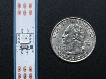
Identify the "input" end of your NeoPixel strip, pixel(s) or other device. On some, there wilbe a solder pad labeled "DIN" or "DI" (data input). Others wil have an arrow showing thedirection that data moves. The data input can originate from any digital pin on the Arduino,but al the example code is set up for digital pin 6 by default. The NeoPixel shield comeswired this way.
If using Flora with an attached lithium-ion battery: connect the +5V input on the
strip to the VBATT pad on Flora, GND from the strip to any GND pad on Flora, and DIN to Flora
pin D6.
Adafruit Industries
For other Arduino boards with a separate +5V DC power supply for the
NeoPixels: connect the +5V input on the strip to the + (positive) terminal on the power
supply (don't connect to the Arduino), DIN to digital pin 6 on the Arduino, and – (minus or
GND) on the strip must connect to both the minus (–) terminal on the DC supply and a GND
pin on the Arduino (there are usual y several — any wil do).
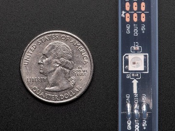
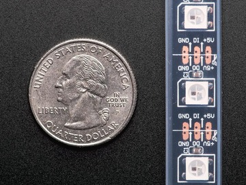
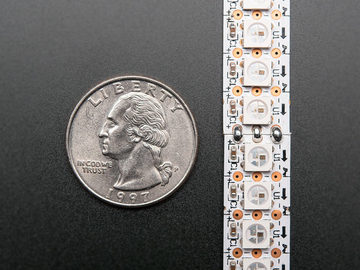
The 144 pixel strips are so tightly packed, there's no room for labels other than –, + and thedata direction arrows. Data is the un-labeled pad.
The order of the three pins can vary between different strip densities and batches.
ALWAYS use the labels printed ON THE STRIP. Look closely, NEVER blindly fol ow aNeoPixel strip wiring diagram; it might be based on a different strip type!
When connecting NeoPixels to any live power source or microcontrol er, ALWAYSCONNECT GROUND (–) BEFORE ANYTHING ELSE. Conversely, disconnect ground lastwhen separating.
Adding a 470 ohm resistor between your microcontrol er's data pin and the data inputon the NeoPixels can help prevent spikes on the data line that can damage your firstpixel. Please add one between your micro and NeoPixels!
Adafruit Industries
We also recommend adding a large capacitor (1000 µF, 6.3V or higher) across the +and – terminals. This prevents the initial onrush of current from damaging the pixels.
See the photo on the next page for an example.
Can NeoPixels be powered directly from the Arduino's 5V pin?
Sometimes. The Arduino can continuously supply only about 500 mil iamps to the 5V
pin. Each NeoPixel can draw up to 60 mil iamps at ful brightness. So yes, you can skip the
separate DC supply and power directly off the Arduino as long as just a few pixels are
used, or more if the colors and overal brightness are low. When in doubt, give the pixels
a separate power supply.
A Simple Code Example: strandtest
Launch the Arduino IDE. From the File menu, select
Sketchbook®Libraries®Adafruit_NeoPixel®strandtest
(If the Adafruit_NeoPixel rol over menu is not present, the library has not been correctlyinstal ed, or the IDE needs to be restarted after instal ation. Check the instal ation stepsabove to confirm it's properly named and located.)
Select your board type and serial port from the Tools menu, and try uploading to the board.
If the NeoPixels are connected and powered, you should see a little light show.
Check your connections. The most common mistake is connecting to the output end of astrip rather than the input.
Let's look at the code now…
Al NeoPixel sketches begin by including the header file:
The block of code that fol ows is mostly descriptive comments. Only the last line is real ydoing any work:
// Parameter 1 = number of pixels in strip// Parameter 2 = pin number (most are valid)// Parameter 3 = pixel type flags, add together as needed:// NEO_KHZ800 800 KHz bitstream (most NeoPixel products w/WS2812 LEDs)// NEO_KHZ400 400 KHz (classic 'v1' (not v2) FLORA pixels, WS2811 drivers)
Adafruit Industries
// NEO_GRB Pixels are wired for GRB bitstream (most NeoPixel products)// NEO_RGB Pixels are wired for RGB bitstream (v1 FLORA pixels, not v2)Adafruit_NeoPixel strip = Adafruit_NeoPixel(60, PIN, NEO_GRB + NEO_KHZ800);
The first line assigns a number to the symbol "PIN" for later reference. It doesn't need to bedone this way, but makes it easier to change the pin where the NeoPixels are connectedwithout digging deeper into the code.
The last line declares a NeoPixel object. We'l refer to this by name later to control the stripof pixels. There are three parameters or arguments in parenthesis:
1. The number of sequential NeoPixels in the strip. In the example this is set to 60, equal
to 1 meter of medium-density strip. Change this to match the actual number you'reusing.
2. The pin number to which the NeoPixel strip (or other device) is connected. Normal y
this would be a number, but we previously declared the symbol PIN to refer to it byname here.
3. A value indicating the type of NeoPixels that are connected. In most cases you
can leave this off and pass just two arguments; the example code is just
being extra descriptive. If you have a supply of classic "V1" Flora pixels, those require
NEO_KHZ400 + NEO_RGB to be passed here.
For through-hole 8mm NeoPixels, use NEO_RGB instead of NEO_GRB in the stripdeclaration.
Then, in the setup() function, cal begin() to prepare the data pin for NeoPixel output:
void setup() { strip.begin(); strip.show(); // Initialize al pixels to 'off'}
The second line, strip.show(), isn't absolutely necessary, it's just there to be thorough. Thatfunction pushes data out to the pixels…since no colors have been set yet, this initializes althe NeoPixels to an initial "off" state in case some were left lit by a prior program.
In the strandtest example, loop() doesn't set any pixel colors on its own — it cal s otherfunctions that create animated effects. So let's ignore it for now and look ahead, inside theindividual functions, to see how the strip is control ed.
There are two ways to set the color of a pixel. The first is:
Adafruit Industries
strip.setPixelColor(n, red, green, blue);
The first argument — n in this example — is the pixel number along the strip, starting from 0closest to the Arduino. If you have a strip of 30 pixels, they're numbered 0 through 29. It's acomputer thing. You'l see various places in the code using a for loop, passing the loopcounter variable as the pixel number to this function, to set the values of multiple pixels.
The next three arguments are the pixel color, expressed as red, green and blue brightnesslevels, where 0 is dimmest (off) and 255 is maximum brightness.
To set the 12th pixel (#11, counting from 0) to magenta (red + blue), you could write:
strip.setPixelColor(11, 255, 0, 255);
An alternate syntax has just two arguments:
Here, color is a 32-bit type that merges the red, green and blue values into a single number.
This is sometimes easier or faster for some (but not al ) programs to work with; you'l seethe strandtest code uses both syntaxes in different places.
You can also convert separate red, green and blue values into a single 32-bit type for lateruse:
uint32_t magenta = strip.Color(255, 0, 255);
Then later you can just pass "magenta" as an argument to setPixelColor rather than theseparate red, green and blue numbers every time.
setPixelColor() does not have an immediate effect on the LEDs. To "push" the color data tothe strip, cal show():
This updates the whole strip at once, and despite the extra step is actual y a good thing. Ifevery cal to setPixelColor() had an immediate effect, animation would appear jumpy ratherthan buttery smooth.
You can query the color of a previously-set pixel using getPixelColor():
Adafruit Industries
uint32_t color = strip.getPixelColor(11);
This returns a 32-bit merged color value.
The number of pixels in a previously-declared strip can be queried using numPixels():
uint16_t n = strip.numPixels();
The overal brightness of al the LEDs can be adjusted using setBrightness(). This takes asingle argument, a number in the range 0 (off) to 255 (max brightness). For example, to set astrip to 1/4 brightness:
Just like setPixel(), this does not have an immediate effect. You need to fol ow this
with a cal to show().
You can't move from a lower brightness to a higher setting without some loss in fidelity.
Certain animation effects are better served by leaving the brightness at max and cal ingsetPixel() repeatedly to fil the strip.
I'm cal ing setPixel() but nothing's happening!
There are two main culprits for this:
1. forgetting to cal strip.begin() in setup().
2. forgetting to cal strip.show() after setting pixel colors.
Another (less common) possibility is running out of RAM — see the last section below. Ifthe program sort of works but has unpredictable results, consider that.
Can I have multiple NeoPixel objects on different pins?
Certainly! Each requires its own declaration with a unique name:
Adafruit_NeoPixel strip_a = Adafruit_NeoPixel(16, 5);Adafruit_NeoPixel strip_b = Adafruit_NeoPixel(16, 6);
The above declares two distinct NeoPixel objects, one each on pins 5 and 6, each containing16 pixels and using the implied default type (NEO_KHZ800 + NEO_GRB).
Can I connect multiple NeoPixel strips to the same Arduino pin?
In many cases, yes. Al the strips wil then show exactly the same thing. This only worksup to a point though…four strips on a single pin is a good and reliable number. If you needmore than that, individual NeoPixels can be used as buffers to "fan out" to more strips:connect one Arduino pin to the inputs of four separate NeoPixels, then connect each
Adafruit Industries
pixels' output to the inputs of four strips (or fewer, if you don't need quite that many). Ifthe strips are 10 pixels long, declare the NeoPixel object as having 11 pixels. The extra"buffer" pixels wil be at position #0 — just leave them turned off — and the strips thenrun from positions 1 through 10.
I'm getting the wrong colors. Red and blue are swapped!
When using through-hole 8mm NeoPixels (or V1 Flora pixels), use NEO_RGB for the thirdparameter in the Adafruit_NeoPixel declaration. For al other types of NeoPixels, useNEO_GRB.
Pixels Gobble RAMEach NeoPixel requires about 3 bytes of RAM. This doesn't sound like very much, but whenyou start using dozens or even hundreds of pixels, and consider that the mainstreamArduino Uno only has 2 kilobytes of RAM (often much less after other libraries stake theirclaim), this can be a real problem!
For using real y large numbers of LEDs, you might need to step up to a more potent boardlike the Arduino Mega or Due. But if you're close and need just a little extra space, you can
Adafruit Industries
Powering NeoPixels
When connecting NeoPixels to any live power source or microcontrol er, ALWAYSCONNECT GROUND (–) BEFORE ANYTHING ELSE. Conversely, disconnect ground lastwhen separating.
Adding a 300 to 500 Ohm resistor between your microcontrol er's data pin and the datainput on the first NeoPixel can help prevent voltage spikes that might otherwisedamage your first pixel. Please add one between your micro and NeoPixels!
NeoPixels are usual y described as "5 Volt devices," but the reality is a little more nuancedthan that.
Some (not al ) NeoPixel products can work with slightly higher voltages. This depends on the
additional support components around the chip, based on available space, cost and the
most likely application. Refer to the specific product description page for
guidance on acceptable voltage limits for each type. When in doubt, aim for 5
Volts.
Lower voltages are always acceptable, with the caveat that the LEDs wil be slightly
dimmer. There's a limit below which the LED wil fail to light, or wil start to show the wrong
color.
Before connecting a NeoPixel strip to
ANY source of power, we very strongly
recommend adding a large capacitor
(1000 µF, 6.3V or higher) across the +
and – terminals. This prevents the
initial onrush of current from damaging
the pixels.
Adafruit Industries
For many wearable projects we recommend a (http://adafru.it/328).
These deliver 3.7 Volts — perfect for directlyfeeding low-power microcontrol ers such as theAdafruit Flora, yet enough voltage to run a shortlength of NeoPixels.
Three alkaline cel s (such as AA batteries) can71) to provide 4.5Volts. Though larger and heaver than the fancylithium-polymer pack, they're inexpensive andreadily available.
Four nickel-metal hydride (NiMH) rechargeableVolts.
Make sure you only use NiMH cells in
this configuration. Four alkaline cel s (the
disposable type) wil output 6V total — that's
too high for some NeoPixels, and definitely too
much for the microcontrol er!
Battery-operated LED project planning is discussed in greater detail in
Adafruit Industries
For most non-portable "desktop" projects, a276) is ideal. This smal2 Amp supply is good for a a meter or so ofNeoPixel strip. We'l explain larger projects in amoment.
Be extremely cautious with bench
power supplies. Some — even reputable,
wel -regarded brands — can produce a large
voltage spike when initial y switched on,
instantly destroying your NeoPixels!
If you use a bench supply, do not connectNeoPixels directly. Turn on the power supplyfirst, let the voltage stabilize, then connect thepixels (GND first).
Estimating Power RequirementsEach individual NeoPixel draws up to 60 mil iamps at maximum brightness white (red + green+ blue). In actual use though, it's rare for al pixels to be turned on that way. When mixingcolors and displaying animations, the current draw wil be much less. It's impossible toestimate a single number for al circumstances, but we've been using 1/3 this (20 mA perpixel) as a gross rule of thumb with no il effects. But if you know for a fact that you needevery pixel on at maximum brightness, use the ful 60 mA figure.
To estimate power supply needs, multiply the number of pixels by 20, then divide the resultby 1,000 for the "rule of thumb" power supply rating in Amps. Or use 60 (instead of 20) ifyou want to guarantee an absolute margin of safety for al situations. For example:
Adafruit Industries
60 NeoPixels × 20 mA ÷ 1,000 = 1.2 Amps minimum60 NeoPixels × 60 mA ÷ 1,000 = 3.6 Amps minimum
The choice of "overhead" in your power supply is up to you. Maximum safety and reliabilityare achieved with a more generously-sized power supply, and this is what we recommend.
Most power supplies can briefly push a little extra current for short periods. Many contain athermal fuse and wil simply shut down if overworked. So they may technical y work, but thisis the electronics equivalent of abusing a rental car.
I estimate I need a 3.6 Amp power supply. I have a 10 Amp supply on-hand. Wil thiscause my NeoPixels to explode?
As long as the output is 5 Volts DC, you're golden. The LEDs wil only draw as muchcurrent (Amperes) as they need. So extra Amps are OK — in fact, it can be a good thing.
The larger power supply wil run cooler because it's not being pushed to its limit.
Excessive voltage, however, wil definitely kil your LEDs.
Extra Amps = good. Extra Volts = bad.
What about batteries and "Amp hours"?
Amp-hours are current over time. A 2,600 mAh (mil iamp-hour) battery can be thought of
as delivering 2.6 Amps continuously for one hour, or 1.3 Amps for 2 hours, and so forth. In
reality, it's not quite linear like that; most batteries have disproportional y shorter run
times with a heavy load. Also, most batteries won't take kindly to being discharged in an
hour — this can even be dangerous! Select a battery sufficiently large that it wil
take at least a couple hours to run down. It's both safer for you and better for the
longevity of the battery.
I need to power LOTS of NeoPixels and don't have a power supply that large. Can I useseveral smal er ones?
Maybe. There are benefits to using a single supply, and large power supplies are
discussed below. "Non-optimal" doesn't necessarily mean "pessimal" though, and we
wouldn't discourage anyone from using what resources they have.
If you go this route, the key is to have al of the ground pins among the strips connectedin common, but the +5V from each power supply should be connected only to one lengthof NeoPixels — those should not al be joined. Every power supply is a little different —not precisely 5 Volts — and this keeps some from back-feeding into others.
Giant Power Supplies
Adafruit offers 5V DC power supplies up to (http://adafru.it/658). This is usual ysufficient for a couple hundred NeoPixels or more. For really large instal ations, you'l need tolook elsewhere.
One possibility is to repurpose an ATX computer power supply. The nice beefy server types
Adafruit Industries
often provide up to 30 Amps. Some minor modifications are needed…Google around for"ATX power supply hack." Note that the ATX 5V rail can be very unstable if there's no loadon the 12V rail!
Even larger (and scarier, and much more expensive) are laboratory power supplies withratings into the hundreds of Amps. Sometimes this is what's needed for architectural scaleprojects and large stage productions. And occasional y we get requests for help…
Please note that projects of this scale are potentially very dangerous, and the
problems of power distribution are fundamental y different than hobby-scale projects. As
much as we enjoy helping our customers in the forums, they are for product technical
support and not ful -on engineering services. If you're developing a project of this scope,
hire a professional electrician with experience in high-power, low-voltage systems such as
photovoltaics or large RVs and boats. This is no charade.
Distributing PowerThe longer a wire is, the more resistance it has. The more resistance, the more voltagedrops along its length. If voltage drops too far, the color of NeoPixels can be affected.
Consider a ful 4 meter reel of NeoPixels. With 5V applied at one end of the strip, for thosepixels closest to this end, power traverses only a few inches of copper. But at the far end ofthe strip, power traverses 8 meters of copper — 4 meters out on the +5V line, 4 metersback on the ground line. Those furthest pixels wil be tinted brown due to the voltage drop(blue and green LEDs require higher voltage than red).
Pro Tip: NeoPixels don't care what end they receive power from. Though data moves in
only one direction, electricity can go either way. You can connect power at the head, the tail,
in the middle, or ideal y distribute it to several points. Try to aim for about 1 meter lengths
for the best color consistency. With larger NeoPixel setups, think of power distribution as
branches of a tree rather than one continuous line.
Adafruit Industries
Resistance is just as much a concern on tinyprojects too!
For wearable electronics we like conductivethread…it's flexible and withstands handwashing. Downside is that it doesn't carry muchcurrent. Here several strands of conductivethread have been grouped to provide bettercapacity for the + and – conductors down a pairof suspenders.
fru.it/ciD) guide.)
Driving 5V NeoPixels from 3.3V Microcontrollers
Increasingly, microcontrol ers are running at 3.3 Volts instead of 5 Volts.That's great news forefficiency, but can present a communication problem with 5V NeoPixels. The 3.3V signalfrom the microcontrol er may not be "loud" enough to register with the higher-voltagedevice. The manufacturer recommends a minimum signal voltage of 70% of the NeoPixelvoltage.
There are two ways this can be addressed:
1. Lower the voltage to the NeoPixels so it's closer (or equal) to that of the
microcontrol er. This is why we recommend LiPo batteries for FLORA projects: 3.7V isenough to run a short length of pixels, and the microcontrol er is comfortable at thatvoltage as wel .
2. Use a (http://adafru.it/735) to step up the signal from the
microcontrol er to the first pixel.
Adafruit Industries
NeoMatrix Library
The Adafruit_NeoMatrix library builds upon Adafruit_NeoPixel to create two-dimensionalgraphic displays using NeoPixels. You can then easily draw shapes, text and animationwithout having to calculate every X/Y pixel position. Smal NeoPixel matrices are available inthe shop. Larger displays can be formed using sections of NeoPixel strip, as shown in thephoto above.
In addition to the Adafruit_NeoPixel library (which was already downloaded and instal ed in aprior step), NeoMatrix requires two additional libraries:
If you've previously used any Adafruit LCD or OLED displays, you might already have thelatter library instal ed.
Instal ation for both is similar to Adafruit_NeoPixel before: unzip, make sure the folder namematches the .cpp and .h files within, then move to your Arduino libraries folder and restartthe IDE.
Arduino sketches need to include al three headers just to use this library:
#include <Adafruit_GFX.h>#include <Adafruit_NeoMatrix.h>#include <Adafruit_NeoPixel.h>#ifndef PSTR #define PSTR // Make Arduino Due happy#endif
Adafruit Industries
The extra ifdef/define/endif lines are only needed if you're using an Arduino Due. Otherwisethey can be left out.
LayoutsAdafruit_NeoMatrix uses exactly the same coordinate system, color functions and graphicsAdafruit_NeoMatrix library.
We'l just focus on the constructor here — how to declare a two-dimensional display madefrom NeoPixels. Powering the beast is another matter, covered on the prior page.
The library handles both single matrices — al NeoPixels in a single uniform grid — and tiledmatrices — multiple grids combined into a larger display:
Let's begin with the declaration for a single matrix, because it's simpler to explain. We'l bedemonstrating the NeoPixel Shield for Arduino in this case — an 8x5 matrix of NeoPixels.
When looking at this shield with the text in a readable orientation, the first pixel, #0, is at thetop left. Each successive pixel is right one position — pixel 1 is directly to the right of pixel 0,and so forth. At the end of each row, the next pixel is at the left side of the next row. Thisisn't something we decide in code…it's how the NeoPixels are hard-wired in the circuit boardcomprising the shield.
Adafruit Industries
We refer to this layout as row major and progressive. Row major means the pixels arearranged in horizontal lines (the opposite, in vertical lines, is column major). Progressivemeans each row proceeds in the same direction. Some matrices wil reverse direction oneach row, as it can be easier to wire that way. We cal that a zigzag layout.
However…for this example, we want to use the shield in the "tal " direction, so the Arduino isstanding up on the desk with the USB cable at the top. When we turn the board this way, thematrix layout changes…
Adafruit Industries
Now the first pixel is at the top right. Pixels increment top-to-bottom — it's now column
major. The order of the columns is stil progressive though.
We declare the matrix thusly:
Adafruit_NeoMatrix matrix = Adafruit_NeoMatrix(5, 8, 6, NEO_MATRIX_TOP + NEO_MATRIX_RIGHT + NEO_MATRIX_COLUMNS + NEO_MATRIX_PROGRESSIVE, NEO_GRB + NEO_KHZ800);
The first two arguments — 5 and 8 — are the width and height of the matrix, in pixels. Thethird argument — 6 — is the pin number to which the NeoPixels are connected. On the shieldthis is hard-wired to digital pin 6, but standalone matrices are free to use other pins.
Adafruit Industries
The next argument is the interesting one. This indicates where the first pixel in the matrix ispositioned and the arrangement of rows or columns. The first pixel must be at one of thefour corners; which corner is indicated by adding either NEO_MATRIX_TOP orNEO_MATRIX_BOTTOM to either NEO_MATRIX_LEFT or NEO_MATRIX_RIGHT. The row/columnarrangement is indicated by further adding either NEO_MATRIX_COLUMNS orNEO_MATRIX_ROWS to either NEO_MATRIX_PROGRESSIVE or NEO_MATRIX_ZIGZAG. Thesevalues are al added to form a single value as in the above code.
NEO_MATRIX_TOP + NEO_MATRIX_RIGHT + NEO_MATRIX_COLUMNS +NEO_MATRIX_PROGRESSIVE
The last argument is exactly the same as with the NeoPixel library, indicating the type of LEDpixels being used. In the majority of cases with the latest NeoPixel products, you can simplyleave this argument off…the example code is just being extra descriptive.
The point of this setup is that the rest of the sketch never needs to think
about the layout of the matrix. Coordinate (0,0) for drawing graphics will
always be at the top-left, regardless of the actual position of the first
NeoPixel.
Why not just use the rotation feature in Adafruit_GFX?
Adafruit_GFX only handles rotation. Though it would handle our example above, it doesn'tcover every permutation of rotation and mirroring that may occur with certain matrixlayouts, not to mention the zig-zag capability, or this next bit…
Tiled MatricesA tiled matrix is comprised of multiple smal er NeoPixel matrices. This is sometimes easierfor assembly or for distributing power. Al of the sub-matrices need to be the same size,and must be ordered in a predictable manner. The Adafruit_NeoMatrix() constructor thenreceives some additional arguments:
Adafruit_NeoMatrix matrix = Adafruit_NeoMatrix( matrixWidth, matrixHeight, tilesX, tilesY, pin, matrixType, ledType);
The first two arguments are the width and height, in pixels, of each tiled sub-matrix, not theentire display.
The next two arguments are the number of tiles, in the horizontal and vertical direction. Thedimensions of the overal display then wil always be a multiple of the sub-matrix dimensions.
The fifth argument is the pin number, same as before and as with the NeoPixel library. Thelast argument also fol ows prior behaviors, and in most cases can be left off.
The second-to-last argument though…this gets complicated…
Adafruit Industries
With a single matrix, there was a starting corner, a major axis (rows or columns) and a linesequence (progressive or zigzag). This is now doubled — similar information is needed bothfor the pixel order within the individual tiles, and the overal arrangement of tiles in thedisplay. As before, we add up a list of symbols to produce a single argument describing thedisplay format.
The NEO_MATRIX_* symbols work the same as in the prior single-matrix case, and now referto the individual sub-matrices within the overal display. Al tiles must fol ow the same format.
An additional set of symbols work similarly to then describe the tile order.
The first tile must be located at one of the four corners. Add either NEO_TILE_TOP orNEO_TILE_BOTTOM and NEO_TILE_LEFT or NEO_TILE_RIGHT to indicate the position of thefirst tile. This is independent of the position of the first pixel within the tiles; they can bedifferent corners.
Tiles can be arranged in horizontal rows or vertical columns. Again this is independent of thepixel order within the tiles. Add either NEO_TILE_ROWS or NEO_TILE_COLUMNS.
Final y, rows or columns of tiles may be arranged in progressive or zigzag order; that is,
every row or column proceeds in the same order, or alternating rows/columns switch
direction. Add either NEO_TILE_PROGRESSIVE or NEO_TILE_ZIGZAG to indicate the order.
BUT…if NEO_TILE_ZIGZAG order is selected, alternate lines of tiles must be rotated 180
degrees. This is intentional and by design; it keeps the tile-to-tile wiring more consistent and
simple. This rotation is not required for NEO_TILE_PROGRESSIVE.
Tiles don't need to be square! The above is just one possible layout. The display shown atthe top of this page is three 10x8 tiles assembled from NeoPixel strip.
Adafruit Industries
Once the matrix is defined, the remainder of the project is similar to Adafruit_NeoPixel.
Remember to use matrix.begin() in the setup() function and matrix.show() to update thedisplay after drawing. The setBrightness() function is also available. The library includes acouple of example sketches for reference.
Other LayoutsFor any other cases that are not uniformly tiled, you can provide your own function to remapX/Y coordinates to NeoPixel strip indices. This function should accept two unsigned 16-bitarguments (pixel X, Y coordinates) and return an unsigned 16-bit value (corresponding stripindex). The simplest row-major progressive function might resemble this:
uint16_t myRemapFn(uint16_t x, uint16_t y) { return WIDTH * y + x;}
That's a crude example. Yours might be designed for pixels arranged in a spiral (easywiring), or a Hilbert curve.
The function is then enabled using setRemapFunction():
RAM AgainOn a per-pixel basis, Adafruit_NeoMatrix is no more memory-hungry than Adafruit_NeoPixel,requiring 3 bytes of RAM per pixel. But the number of pixels in a two-dimensional displaytakes off exponential y…a 16x16 display requires four times the memory of an 8x8 display,or about 768 bytes of RAM (nearly half the available space on an Arduino Uno). It can beanywhere from tricky to impossible to combine large displays with memory-hungry librariessuch as SD or ffft.
Gamma CorrectionBecause the Adafruit_GFX library was original y designed for LCDs (having limited colorfidelity), it handles colors as 16-bit values (rather than the ful 24 bits that NeoPixels arecapable of). This is not the big loss it might seem. A quirk of human vision makes brightcolors less discernible than dim ones. The Adafruit_NeoMatrix library uses gammacorrection to select brightness levels that are visual y (though not numerical y) equidistant.
There are 32 levels for red and blue, 64 levels for green.
The Color() function performs the necessary conversion; you don't need to do any math. Itaccepts 8-bit red, green and blue values, and returns a gamma-corrected 16-bit color thatcan then be passed to other drawing functions.
Adafruit Industries
Adafruit Industries
Help! My Arduino servo code stops working when combined with NeoPixels!
Unfortunately the NeoPixel and Servo libraries don't play nice together; one is dependenton periodical y disabling interrupts, the other absolutely requires interrupts. There are acouple of options here:
nterruptsare a non-issue.
Use a (http://adafru.it/eda) rather than the stockArduino Servo library. This can provide rock-steady servo timing without interrupts,but can only control a very limited number of servos (2-3), and only on very specificpins.
How fast can I refresh a string of (N) pixels?
NeoPixels receive data from a fixed-frequency 800 KHz datastream (except for "V1"Flora pixels, which use 400 KHz). One bit therefore requires 1/800,000 sec — 1.25microseconds. One pixel requires 24 bits (8 bits each for red, green blue) — 30microseconds. After the last pixel's worth of data is issued, the stream must stop for atleast 50 microseconds for the new colors to "latch."
For a strip of 100 pixels, that's (100 * 30) + 50, or 3,050 microseconds. 1,000,000 /3,050 = 328 updates per second, approximately.
That's only the time needed to push the bits down the wire. The actual refresh rate wilbe something less than this, and can't be estimated as a single number for al cases. Ittakes time to process each "frame" of animation. How much time depends on thecomplexity of the math and the efficiency of the code (for example, floating-pointcalculations can be relatively slow). The technique above gives a maximum theoreticalrate, but that's just a starting point. Reality in some cases could fal an order of magnitude(or more) below this.
For exploratory benchmarking, you can always write code as if a large number of pixelswere present, and time the result. The extra output bits wil simply be ignored by the strip(or you can even test with no NeoPixels connected at al ).
That won't do. Now what?
Because NeoPixels use a fixed-frequency clock, options are limited. You can't switch outfor a faster microcontrol er and expect substantial y different results.
One option is to use a different LED type, such as our LPD8806 strips or WS2801 pixels.
These can be driven at higher data rates, though they do have some other tradeoffs withrespect to NeoPixels (cost, color resolution and/or pixel density).
Adafruit Industries
Another is to develop your own code for a more capable microcontrol er or an FPGA thatdrives multiple NeoPixel strips in parallel. One such project — OctoWS2811 for theTeensy 3.0 microcontrol er — is shown later. This sort of thing is a complex undertakingand not recommended for beginners. And even among more experienced programmers,there's often an unreasonable over-emphasis on data rates when the real bottlenecks lieelsewhere…don't dwel on this too much unless you can confirm it's a problem.
Can I control NeoPixels using (Board X)?
We currently only offer an Arduino library. See the links later for other devices. Foranything beyond this, if considering writing your own library, understand that somedevices are better suited to the task than others. Read through the timing requirementsshown below and determine if the processor or device in question can synthesize asignal meeting those specifications. An 8 MHz AVR can just barely keep up…anythingslower may have trouble, though some hardware-specific hacks (like clever use of SPI)might make it possible. In many cases, assembly language is required.
Why not Raspberry Pi?
The Raspberry Pi running Linux is a multitasking system, and control may switch amongmultiple running programs at any time. As such, it's impossible to guarantee the strict 800KHz signal required by NeoPixels. You may be able to fudge it for short intervals, but it'snot something that can be counted upon. This is why we use LPD8806 pixels for the (http://adafru.it/aPk) demonstration.
Third-Party LibrariesNeoPixel-compatible libraries have been developed for devices beyond Arduino. Pleasekeep in mind that Adafruit did not develop any of this code, does not know it inside and out,and can't fix bugs or offer technical help. This is Wild West stuff.
(http://adafru.it/cDM): specifical y for the PJRC Teensy 3.0
microcontrol er board. Uses DMA to drive up to 8 NeoPixel strips concurrently with
minimal processor load. Multiple boards can be cascaded for stil larger displays.
(http://adafru.it/cDN): also for Teensy 3.0. Doesn't support as many
pixels as OctoWS2811, but adds smooth interpolation and other features for the color-
persnickety.
(http://adafru.it/cDO): specifical y for BeagleBone Black. Although the
BeagleBone is a multitasking Linux system like the not-NeoPixel-compatible Raspberry
Pi, this code exploits hardware features specific to the BeagleBone Black to drive
hundreds of meters of NeoPixel strip with virtual y no processor load.
(http://adafru.it/cDP) for Paral ax Propel er.
(http://adafru.it/dcO) for the XMOS xCORE startKIT.
Some of these are 3.3V devices. See the "Powering NeoPixel" page for notes oncontrol ing 5V NeoPixels from 3.3V microcontrol ers.
Adafruit Industries
WS2811? WS2812? Why do I see two different names mentioned?
The WS2811 is an earlier driver chip separate from the RGB LED. The data signal is similar,but runs at half the speed. By the time the WS2812 (with integrated LED) was released, alot of code and projects had already built up around the WS2811 name. Sometimes code"for the WS2811" might actual y be for the newer chip, or for either type. TheAdafruit_NeoPixel library supports both.
Writing Your Own Library
The (http://adafru.it/cDB) explains the data transmission protocol. This isa self-clocking signal — there's only one wire, not separate data and clock lines. "1" and "0"bits are indicated by varying the duty cycle of a fixed-frequency square wave.
There's a math goof in the datasheet's timing values. Use these figures instead:
Note that there's nearly 25% "wiggle room" in the timing. So if your code can't match therecommended times exactly, it's usual y okay.
There are three bytes of data for each pixel. These should be issued in green, red, blueorder, with the most-significant bit first.
The data for pixel #0 (nearest the microcontrol er) is issued first, then pixel #1, and so forthto the furthest pixel. This does not operate like a traditional shift register!
Adafruit Industries
After al the color data is sent, the data line must be held low for a minimum of 50microseconds for the new colors to "latch."
You may want to dig through our (http://adafru.it/aZU) for insights. The timing-critial parts are written in AVR assembly language, but it's extensively commented with C-like pseudocode.
My Microcontrol er Isn't Fast Enough to Do That
The WS2812 appears to be backwardly-compatible with the 400 KHz WS2811 signal. If
you can precisely match the latter chip's timing, either type wil respond. The WS2811
protocol is not simply a half-speed WS2812. The duty cycle for the "0" and "1"
bits is slightly different. From the (http://adafru.it/cDS):
Adafruit Industries
Last Updated: 2014-12-02 12:45:16 PM EST
Source: http://www.mouser.ee/pdfdocs/adafruitneopixeluberguide.PDF
Contents Symposium Overview General Information Special Events Symposium Organizers Technical Program Abstracts & Speakers' Biographies Symposium Overview Overview Attendees at the new SAE symposium will take an insightful look at new and developing technologies addressing future CO2 targets. The event will combine state-of-the-art technology presentations with face-to-face networking opportunities for professionals focused on meeting the EU's proposed greenhouse gas targets of 120g CO2/km by 2012 and 95g CO2/km by 2020.
Caja de Herramientaspara el Control Ciudadano de la Corrupción Enseñar Etica a los Jóvenes Ejemplos de 11 países Derechos de Autor La Edición Especial de la Caja de Herramientas: Enseñar Etica a los Jóvenespresenta once iniciativas de educación anticorrupción desarrolladas por losCapítulos Nacionales de Transparency International y otras organizaciones. LaEdición Especial de la Caja de Herramientas sólo puede ser reproducida, entodo o en parte, con la correspondiente autorización y reconocimiento de am-bas fuentes: Transparency International Secretariat y la organización respon-sable del proyecto en cuestión.