Untitled

IEEE TRANSACTIONS ON COMPUTER-AIDED DESIGN OF INTEGRATED CIRCUITS AND SYSTEMS, VOL. 28, NO. 7, JULY 2009
The Tire as an Intelligent Sensor
Sinem Coleri Ergen, Member, IEEE, Alberto Sangiovanni-Vincentelli, Fellow, IEEE, Xuening Sun, Member, IEEE,
Riccardo Tebano, Sayf Alalusi, Giorgio Audisio, and Marco Sabatini
Abstract—Active safety systems are based upon the accurate
and fast estimation of the value of important dynamical variables
such as forces, load transfer, actual tire–road friction (kinetic
friction) μk, and maximum tire–road friction available (potential
friction) μp. Measuring these parameters directly from tires offers
the potential for improving significantly the performance of active
safety systems. We present a distributed architecture for a data-
acquisition system that is based on a number of complex intelligent
sensors inside the tire that form a wireless sensor network with
coordination nodes placed on the body of the car. The design of
this system has been extremely challenging due to the very limited
available energy combined with strict application requirements
for data rate, delay, size, weight, and reliability in a highly dy-
namical environment. Moreover, it required expertise in multiple
engineering disciplines, including control-system design, signal
processing, integrated-circuit design, communications, real-time
360◦ integrated safety.
software design, antenna design, energy scavenging, and system
assembly.
e.g., a mechanical system such as an automobile, a train,
Index Terms—Automotive safety, energy efficiency, energy scav-
or a plane; an electrical system such as an electrical motor
enging, heterogeneous systems, intelligent systems, platform-based
or generator; a chemical system such as a distillation
design, tires, ultrawideband, wireless sensors.
plant; health-care equipment such as a pacemaker; adistributed environment monitoring and control system
or a security system for access control to protectedareas.
THE ELECTRONICS industry ecosystem is undergoing
a radical change driven by an emerging three-layered
In particular, this evolution will have a dramatic effect on
architecture characterized by the following features:
automobiles, particularly when considering safety. Road-trafficinjuries still represent about 25% of worldwide injury-related
1) computing and communication infrastructure that will
deaths (the leading cause) with an estimated 1.2 million deaths
offer increasingly faster data transfer and manipulation
(2004) each year [9]. Passive safety devices, such as crumple
via powerful data centers, compute farms, and wired
zones, seat belts, and airbags, work passively to prevent injuries
and are standards today. Obviously, these devices, albeit effec-
2) access devices such as PDAs, cell phones, and laptops
tive, are nowhere near to preventing accidents. Active safety is
that allow leveraging of the immense capabilities of the
the frontier for original equipment manufacturers and suppliers
infrastructure for users, which can be humans or any of
to eliminate deadly accidents. Active safety systems use infor-
the intelligent physical systems as follows;
mation about the external environment of a vehicle to change
3) a swarm of sensors, actuators, and local computing ca-
its behavior in precrash time period or during the crash event,
pabilities immersed in all kinds of physical systems that
with the ultimate goal of avoiding a crash altogether. The zero-
offer a wide variety of personal or broad-use services,
accident car includes both autonomous systems, such as radar-based crash-avoidance systems, and cooperative systems that
Manuscript received July 14, 2008; revised November 13, 2008. Current
rely on vehicle-to-vehicle and vehicle-to-infrastructure (and
version published June 17, 2009. This work was supported in part by the
vice versa) communication. Eventually, we believe autonomous
Gigascale System Research Center, by the MICRO program of the State ofCalifornia, and by the Artist Design Network of Excellence. This paper was
driving will be possible based on wireless and wired networks
recommended by Associate Editor M. Di Natale.
of powerful sensors (see Fig. 1, courtesy of General Motors)
S. C. Ergen is with the Pirelli/Telecom Italia, Wireless Sensor Networks
and complex control algorithms implemented on a distributed
Berkeley Laboratory, Berkeley, CA 94704 USA.
computing platform. In fact, research efforts into autonomous
A. Sangiovanni-Vincentelli and X. Sun are with the Department of Elec-
trical Engineering and Computer Science, University of California, Berkeley,
accident-free vehicles began in the 1980s with the EUREKA
Berkeley, CA 94720-1500 USA (e-mail: [email protected]).
Prometheus project [7].
R. Tebano, G. Audisio, and M. Sabatini are with Pirelli Tyres S.p.A., 20126
Early work on active safety systems were primarily focused
Milano, Italy (e-mail: [email protected]).
S. Alalusi was with the Pirelli/Telecom Italia, Wireless Sensor Networks
on improving the longitudinal motion dynamics, particularly
Berkeley Laboratory, Berkeley, CA 94704 USA. He is now with TransRobotics,
on more effective antilock braking systems and traction-control
San Francisco Bay Area, Hayward, CA 94545 USA.
(TC) systems. TC systems prevent the wheel from slipping
Color versions of one or more of the figures in this paper are available online
while improving vehicle stability and control by maximizing
Digital Object Identifier 10.1109/TCAD.2009.2022879
the tractive and lateral forces between the vehicle's tire and
0278-0070/$25.00 2009 IEEE
IEEE TRANSACTIONS ON COMPUTER-AIDED DESIGN OF INTEGRATED CIRCUITS AND SYSTEMS, VOL. 28, NO. 7, JULY 2009
the road. This was followed by more powerful vehicle-stability
quantities of interest from accelerometer data is non-
control (VSC) systems, e.g., electronic stability program, VSC,
trivial [8].
and dynamic stability control. These systems use both brakes
3) Since accelerometer data have to be generated/delivered
and engine torque to stabilize the vehicle in extreme handling
at each revolution of the tire, the data-rate requirement
situations by controlling the yaw motion. Active suspension
could quickly deplete any battery that meet the weight
systems are also an important part in active safety systems.
and size requirements. Replacing batteries is obviously
They have been traditionally designed by trading-off three
out of the question because of the difficulty of reaching
conflicting criteria: road holding, load carrying, and passenger
inside the tire. Hence, some sort of energy scavenging is
comfort. The suspension system must support the vehicle,
needed that relies on a transducer of mechanical energy
provide directional control during handling maneuvers, and
into electrical energy via inductive or capacitive coupling
provide effective isolation of passengers/payload from road
or on illuminator technologies based on transferring elec-
tromagnetic power to a remote device via an RF link.
The active safety control systems described earlier are based
These approaches, however, can only provide energy of
upon the estimation of vehicle dynamics variables such as
less than 1 mW/cm2, thus limiting the total energy avail-
forces, load transfer, actual tire–road friction (kinetic friction)
able for sensing, computing, transmission, and reception.
μk, and maximum tire–road friction available (potential fric-
4) The radio link from the tires to the onboard controllers
tion) μp, which is probably the most important parameter for
must be sustainable with limited energy and resilient to
the improvement of vehicle dynamic control systems [10].
the harsh tire environment.
The more accurate and "real time" the parameter estimation
5) The communication protocol between the various ele-
is, the better the overall performance of the control system.
ments of the system has to be carefully designed to use
Currently, most of these variables are indirectly estimated using
the minimum amount of power while making sure that
onboard sensors. With a more accurate estimation, we could
data reach the destination reliably and on time.
even identify road-surface condition in real time. By detecting
In this paper, we describe the analysis and decision processes
the change in the slope of the friction versus slip curve, regions
followed to design a wireless sensing subsystem based on
of slippery surface can be identified [10], [11].
intelligent sensor nodes that are inside the tire and that solve
The Apollo project [1] attempted to gain real-time informa-
the challenges described earlier. The final phase of the design
tion by using the tire as a sensor. However, until recent de-
has not been completed as yet; we are still evaluating and proto-
velopments in low-power wireless communication and energy
typing the energy-scavenging and wireless-communication
scavenging, this approach was expensive and remained mostly
subsystems. In Section II, we present how to extract the in-
in the research domain, since it was not easily adoptable as
formation of interest for safety control from accelerometers.
a consumer product. Currently, state-of-the-art tire monitoring
In Section III, we introduce the overall architecture of the
systems [2]–[6] primarily acquire low-duty cycle data such as
system. Then, in Section IV, we discuss the architecture of
tire pressure, temperature, and/or material strain of the tire.
the intelligent sensor node and describe its components. In the
However, they are not equipped to sense and transmit high-
following sections, we present the most interesting and novel
speed dynamic variables used for real-time active safety control
aspects of the design that refer to the communication scheme:
An ultrawideband (UWB) radio designed specifically for this
In this paper, we describe the considerations, tradeoffs, and
application (Section V) and a new medium-access-control
decisions used to design a real-time system for extracting
(MAC) protocol called implicit-scheduled time-divided MAC
directly from the tire relevant information to improve signif-
(ISTD-MAC) (Section VI). In Section VII, we introduce the
icantly active safety control systems and enable the develop-
methodology followed in the design. In Section VIII, we draw
ment of a wide range of new applications. Placing a sensor
conclusions, and we chart the road for the future full-fledged
system that could compute the quantities of interest in a tire
implementation of the Intelligent Tire Acquisition system.
and transmit this information to a safety controller is a verychallenging proposition for technical, reliability, and economicreasons.
II. EXTRACTING VARIABLES OF INTEREST
In particular, the major challenges to face are as follows.
FROM ACCELEROMETERS
1) The inside of a tire is a harsh environment with high
The information necessary to significantly improve active
accelerations (at 200 km/h, we have an acceleration equal
safety and active dynamics control systems is extracted using
to 3000 g's inside the inner liner) and cannot be reached
data-processing algorithms operating at two distinct levels as
without taking the tire off the wheel. This situation poses
very difficult problems: The high centrifugal accelerationimplies that the sensor be lightweight, robust, and small;
1) Tire Level. They range from simple temperature and
the fact that the tire moves continuously with respect
pressure information extraction to load, lateral, and lon-
to the body of the car forces us to choose a wireless-
gitudinal forces and potential friction estimation based
communication link.
upon more complex accelerometer data processing and
2) Among the available miniaturized sensors, accelerome-
modeling. Tire wear and aquaplaning are also extracted
ters were chosen for our application, since they exhibit a
with algorithms at the tire level.
number of advantages: They are well understood, widely
2) Vehicle Level. They range from load distribution and
available, reliable, accurate, and relatively inexpensive.
dynamic load-transfer estimation to amount of friction
However, devising algorithms that could compute the


ERGEN et al.: TIRE AS AN INTELLIGENT SENSOR
Load transfer during multiple acceleration–deceleration maneuvers.
Circles represent the estimated load transfer with the Intelligent Tire systemwhile the solid line is the traditional load-estimation method based upon sensorson vehicle.
This section gives an overview of how relevant data at these
two levels are obtained from raw sensor data.
In Fig. 2, we show the method proposed to estimate forces
and kinetic friction, Fx, Fy, Fz, and μk along with other im-portant tire–road dynamic interaction parameters, i.e., potentialfriction μp and tire slip σ, using the measurements providedby the accelerometers in the sensor nodes. The key aspect ofthe extraction method is the analysis of the dynamics of thecontact patch area of the tire. This dynamics contains specific
information about the variables earlier.
The first stage derives the tire kinematics by solving the
collected is the computation of the vehicle load transfer in
corresponding equations of motion, i.e., by double integration
nonstationary dynamic maneuvers consisting of multiple ac-
of accelerations as measured by the accelerometers and with
celeration and deceleration sequences. Fig. 3 shows the load-
proper boundary conditions. From this and some key tire pa-
transfer estimation obtained with the Intelligent Tire system
rameters, we obtain the "experimental" dynamics in the patch
versus the conventional load-estimation method based upon
area, i.e., the area of the tire that is in contact with the ground
sensors located on the vehicle. In addition, the Intelligent Tire
from which we can obtain the forces of interest.
Acquisition system allows the distinguishing of single-tire load
To obtain the other important parameters such as the potential
friction, we need a fairly complex path as described in thefigure. To do so, we developed an ad hoc tire physical model
III. SYSTEM ARCHITECTURE
that includes parameters that are typical of the particular tireconsidered and of the dynamical condition of the car. At this
Fig. 4 shows the architecture of the tire sensor network. The
second stage, the dynamics of the contact-patch-area tire defor-
main components of the system are organized in a hierarchical
mations are obtained using a theoretical tire force–deformation
manner in a personal area network (PAN) defined as a collection
frame. The potential friction is a parameter for the calculation
of cooperating devices, which are associated and share the same
of the deformations of the patch area.
address space. At the lowest level, sensor nodes, located inside
The last stage identifies the correct value of the theoretical
the tires, are responsible for data acquisition, processing, and
model parameters (e.g., μk) by "fitting" them so that the results
transmission to the in-vehicle equipment. Placing more than
of the theoretical model "match" the ones obtained by measure-
one sensor inside each tire achieves increased accuracy and
ments. This is done by finding the values of the parameters so
reliability of the measurements performed. For example, three
that an appropriate metric defined to evaluate the "difference"
sensor devices may be located at an angle of 120◦ with respect
between the output of the theoretical model and the measured
to each other. This configuration allows improved knowledge
results is minimized as is customary in identification problems.
of spatial variation of tire/road interaction parameters, albeit
There are, of course, several metrics that can be used to mea-
the availability to the vehicle dynamics control system of this
sure the difference of the outputs: For example, the minimum
"knowledge" is subject to a time delay of half a wheel turn,
of the maximum difference over the set of experiments or
independent of the number of sensor nodes inside the tire.
the sum of the squares of the differences at every point of the
The PAN coordinator at the upper level of the hierarchy is
test set. The metrics to be used is a compromise between the
mounted in the vehicle and powered by the vehicle main. It
computational burden and the accuracy of the final result. In
manages the communication with the sensor nodes in the same
preliminary experiments, we obtain an error in the important
tire, receives data from them, and is the master of synchroniza-
parameters on the order of 5%.
tion. PAN coordinators can be connected to each other via a
The data collected by the Intelligent Tire can be used in
wired network or even a vehicle system bus such as CAN and
multiple ways. An example of the information that can be
FlexRay. The highest layer of the network is the System Control

IEEE TRANSACTIONS ON COMPUTER-AIDED DESIGN OF INTEGRATED CIRCUITS AND SYSTEMS, VOL. 28, NO. 7, JULY 2009
The design of each component of the Intelligent Tire is
nontrivial but the radio link and the power generation andmanagement system are by far the most challenging. In thefollowing sections, we describe details of each of the compo-nents together with the challenges to be considered in systemassembly.
A. Power-Supply Subsystem
The most common way of providing power to wireless
devices is storing chemical energy in a battery. In battery tech-nologies, however, the lifetime of the node will be determinedby the fixed amount of energy stored on the device regardless ofthe form of energy storage. There is no known battery chemistrythat can deliver the necessary amount of energy for the volumeavailable. Furthermore, the accelerations involved and the high-temperature requirements make battery technology unfeasiblefor this application.
Since energy storage in the nodes is impossible, alternative
methods of providing power fall into one of two categories.
1) Scavenging available power at the node [28]. The most
suitable technology for the tire system relies on scaveng-ing power from vibrations. Devices include electromag-netic, electrostatic, and piezoelectric methods to convertmechanical motion into electricity. The amount of powergenerated by the scavenger depends on the technology
chosen, on the size of the scavenger, and on the environ-mental conditions such as vibrations, elongation stresses,
Host. This device is responsible for coordinating all PAN
and temperature gradients. These approaches provide
coordinators, interfacing them with the vehicle main control
energy levels in 10–200-μW range for real-world tire
and providing a bridge to the vehicle system bus. The System
scenarios. It is conceivable that, due to strong market
Control Host is responsible for transferring commands to the
demands, progress will be made in terms of power output.
sensor nodes from the vehicle main control and information
2) Electromagnetic coupling. The possible methods of pro-
acquired by the PAN coordinators to the vehicle main control
viding electromagnetic wireless power transfer include
via the vehicle system bus. The System Control Host may be
magnetic field coupling via inductive action between two
implemented as one of the PAN coordinators, having enhanced
coils, magnetic field coupling via self-resonant coils, and
functions with respect to other coordinators.
microwave radiation beam via highly directive antennas.
The resulting network architecture has a cluster-tree struc-
An illuminator is a main-powered antenna transferring
ture. We chose to have one PAN coordinator corresponding
electromagnetic power to a remote device via an RF link.
to each tire instead of a common coordinator, since by doing
Power is collected by the remote device by means of
so, we increase the total throughput by limiting the number of
a suitable receiving antenna. This technique is used for
sensors controlled by each coordinator, and we minimize the
RFID applications. In our case, the illuminator would
distance between sensor nodes and PAN coordinator for a more
have to be placed on the wheel as well so that the amount
robust communication. A cluster-tree structure is suitable for
of energy delivered is optimized.
this application, since sensor nodes need not communicate with
We are currently investigating both possibilities. Other
each other but only with the PAN coordinator.
means of transferring power to the nodes such as acousticemitters and lasers are not suitable for tire systems due to poor
transmission through the tire.
The sensor node (see Fig. 5) is the in-tire device with the
Both alternatives provide a time-dependent power, since
tasks of acquiring data from the tire, executing preliminary
power generation and coupling is strictly related to the wheel
digital signal processor (DSP) processing on them, such as
motion and position. Therefore, raw generated power must be
signal conditioning and compensations, and to send data on the
conditioned to provide a power supply that is almost constant,
RF link. The most important requirements of the Intelligent Tire
at least within a complete wheel rotation. It is important to con-
are an unlimited lifetime and a small size. The sensor nodes
sider that, during normal operating conditions, the wheel may
inside the tires should be operational for the lifetime of the tire.
stop its motion and power cannot be supplied any longer: For
Moreover, the technology should satisfy the wide-temperature-
this reason, a power sensing function has to be implemented,
range requirements and robustness to high accelerations: Ex-
such that the microcontroller is informed as soon as power
treme temperatures range from −40 ◦C in winter up to 100 ◦C
supplied becomes insufficient. In this situation, the node goes
in summer time, and an object mounted on inner lining is
into a power-down mode in a controlled and "safe" manner. The
subject to a radial acceleration up to 3000 g's at 200 km/h.
power sensing function determines the start of communication
ERGEN et al.: TIRE AS AN INTELLIGENT SENSOR
in MAC protocol design, as we will see in Section VI. Fur-
mation of the signal acquired by the accelerometers into digital
thermore, the ultra-low power-consumption constraint suggests
signals, as shown in Fig. 5. The acquisition path provides an
that acquisition, reception, and transmission phases are kept
analog section and a digital section.
separated as much as possible to spread power consumption oneach wheel round and avoid high consumption peaks caused by
1) The analog section amplifies and filters the acquired
overlapping different activities. This places timing constraints
signal. Then, analog data are converted and passed to a
on the sensing and communication functions.
digital section. Oversampling techniques may be used;thus, signals may be acquired at sampling frequencieshigher than their final sampling rate.
B. Sensor- and Acquisition-Path Subsystems
2) The digital section is responsible for signal conditioning
The sensor is a triaxial accelerometer, mounted inside the tire
for correcting accelerometer imperfections such as offset
on top of the inner liner, oriented so that the three axes measure
bias and resonant-frequency compensation. Data are sent
signals in the radial, circumferential (tangential), and lateral
to a processing chain that provides filtering and decima-
directions with respect to the tire circumference. Therefore, the
tion to the final sampling rate. Automatic-gain-control
input flow to the sensor node consists of three data streams.
techniques may be used to keep the SNR constant, even
The requirements that drive the choice of technology for the
at low levels of signal dynamics.
accelerometers are reliability and reproducibility, accuracy andresolution, power consumption, size, and cost.
Few available technologies fit all of the requirements
C. Microprocessor Subsystem
listed above. Stringent power requirements exclude the use
A single-core DSP is responsible to manage the communi-
of piezoresistive technology. Today's accelerometers based on
cation protocol; all the functions that control the activity of the
piezoresistive technology have power consumptions in the
sensor nodes, such as command execution, system monitoring,
range of several milliwatts. Even though we may consider a
and diagnostics; and the following typical DSP functions:
custom-built product that could consume up to a few hundredmicrowatts, this technology intrinsically requires a bias so it
1) estimation and compensation of signal nonlinearity;
will always be more power hungry than capacitive or piezo-
2) estimation and compensation of crosstalk among the
electric devices.
The two main piezoelectric non-microelectromechanical-
3) estimation of bias and offset;
system (MEMS)-based technologies are crystal and ceramic
4) data compression for reducing the input throughput;
based. The latter is somewhat smaller given the same g sensitiv-
5) algorithms required by the communication protocol.
ity, although less stable in temperature, and with higher process
Note that some of these algorithms may be implemented
sensitivity spread. This technology is capable of providing the
by specialized HW devices to reduce power consumption and
dynamic range of interest, with reliability indexes suitable for
increase performance if product testing will uncover problems
our application, and it is intrinsically very low power, providing
in these areas.
a charge as an input to the acquisition path satisfying the no-bias-current requirements. However, it is fairly large so it doesnot fit our size requirement.
D. Radio Subsystem
Current MEMS-based technologies include the following
The radio subsystem is responsible for the following
1) piezoelectric technology consisting of deposition of a thin
piezoelectric film of lead titanate onto a MEMS silicon
1) transforming digital data to be sent to the PAN coor-
dinator into analog signals modulated over the desired
2) piezoresistive technology consisting of etching semicon-
transmission channel;
ducting silicon gauges;
2) receiving analog data from the transmission channel and
3) capacitive technology.
transforming them into baseband digital data.
The capacitive technology is the technology of choice, since
The radio subsystem consists of an SW driver and an HW
it is used in airbags with millions of devices shipped annually,
transceiver. The transceiver implements the physical-layer com-
having reached a reliability standard that complies with the de-
ponents, related to channel coding/decoding, modulation and
manding requirements of our tire application. It is also very low
conversions between analog signals to/from digital data, syn-
cost when manufactured in volume and fits the size constraints.
chronization, and generation of events on a fine-grain timescale
The challenge to deploy this technology is to compensate for
(bit or chip level). The SW driver implements the MAC layer
an intrinsic spread of process parameters and high dependences
and higher network layer components and manages all events
of key design parameters such as sensitivity (millivolts or pico-
and synchronization requirements at a coarse-grain timescale
coulombs per g) and offset to temperature and manufacturing
(frame level). Amplifiers are included in the radio channel to
process. The challenge of extracting a wide dynamic range with
increase the power of the signal before transmission or before
the required resolution is responsibility of the circuitry that
processing the received signals. This subsystem is expected to
interfaces the MEMS device. The accelerometers themselves
give significant contribution to the overall power-consumption
are simple devices; all compensations and corrections to the
budget together with the acquisition chain, and for this reason,
sampled signals are provided by the other components of the
its design is of paramount importance. We dedicate the next
sensor node. The acquisition path is responsible for the transfor-
section to a detailed description of the solutions adopted.

IEEE TRANSACTIONS ON COMPUTER-AIDED DESIGN OF INTEGRATED CIRCUITS AND SYSTEMS, VOL. 28, NO. 7, JULY 2009
E. System Assembly
The operating conditions of the sensor nodes place hard con-
straints on the weight and size of each unit. First, the mass of thesensors must be kept minimal so that it does not affect the tirecharacteristics and the accelerometer signals. In addition, sincethe nodes are to be mounted into the rubber of the tire body,its size must be small (around 1 cm3) so that extra mechanicaldevices do not need to be added to the system package formounting. The small-size requirement directly competes withrequirements needed for the antenna and energy scavenger,
Channel measurement setup.
where increased size and mass allow better performance. Thesecompeting constraints create many challenges for system opti-
the tire, composed of a metal mesh and rubber, attenuates the
mization. Furthermore, the high temperature, centrifugal forces,
and mechanical stresses that the system must withstand are
For the channel measurements, a wrecked Hyundai Accent
nontrivial tasks for system assembly.
was purchased, and the right rear quarter of the car was cutoff. The wheel arch and all machinery inside including thesuspension were preserved. The SkyCross UWB antennas are
V. RADIO SUBSYSTEM
placed inside the tire under the tire tread and at the highest pointinside the wheel arch. To generate the transmit signal, a pulse
The communication environment in the Intelligent Tire
generator is used. It is capable of pulses with 100-ps width. To
system is very harsh. For the uplink transmission, UWB
receive the signal, the receive antenna is connected to a pulse
transmission is preferred to narrowband transmission and
amplifier through a short cable. The amplified signal is then sent
spread-spectrum techniques due the presence of severe
to a 20-GS/s 6-GHz input bandwidth oscilloscope. The setup in
multipath and lack of line-of-sight (LOS) [22]. In addition
the Berkeley Wireless Research Center is shown in Fig. 6.
to being robust to intersymbol interference due to multipath
The channel impulse response is based on the modified
fading, the UWB systems hide signals below the noise floor
Saleh–Valenzuela (SV) model developed for UWB systems
causing little or no interference to existing systems and mitigate
[12]. The model consists of clusters that arrive according to a
the performance degradation due to narrowband interference.
Poisson process. The power envelope for the clusters follows an
We specifically utilize impulse-based UWB technology due to
exponential-decay random process. Each cluster is made up of
the simple transmitter architecture, which makes it ideal for the
rays which also arrive according to a Poisson process and decay
low-power high-data-rate uplink transmission from sensor node
according to an exponential random process.
to vehicle. The main drawback is that UWB receiver design is
An initial comparison with the measured data showed that
challenging due to the sensitivity requirements. A low data rate
the SV model matched quite closely once the parameters are
is required for the downlink, so we use narrowband transmis-
set correctly. The only problem was that there was too much
sion and an ultra-low-power receiver on the sensor nodes.
incoming energy at very early times due to the exponentialenvelope. Intuitively, this early time energy is due to a strongLOS or at least significant energy traveling in a geometrically
A. Uplink Communication
straight line from the transmitter to the receiver. In the case of
UWB technology has emerged in recent years as the ideal
the tire channel, the LOS is probably through the tire thread and,
solution for low-cost low-power short-range wireless data trans-
therefore, is very weak. The strongest rays travel through the
mission. FCC defines UWB as any radio technology for which
sidewalls and experience at least one reflection before arriving
the emitted signal bandwidth exceeds the lesser of 500 MHz
at the receiver. Thus, the exponential random envelope for
and 20% of the center frequency [15]. In 2002, FCC has
the cluster arrivals was deemed inappropriate. The base SV
allocated the 3.1–10.6-GHz band for the unlicensed use of
model was modified slightly. The exponential envelope for the
UWB applications; however, these systems must limit energy
cluster power was changed to a Rayleigh random envelope.
emission to follow the FCC spectral mask [16] so that no
The Rayleigh distribution has maximum energy at some time
interference is caused to existing technologies in the band.
greater than zero but usually a small number. In our case, that
To design the UWB system, it is necessary to understand
is a few nanoseconds. All other aspects of the model were
the transmission channel that operates on the transmitted
unchanged: Poisson process for cluster and ray arrival times
signal. There have been studies of typical channels for UWB
and exponential decay of ray power within a cluster. This new
communication systems in indoor and outdoor scenarios. How-
model is referred to as the SV-R model. An instance of the
ever, these environments are much larger than the wavelengths
resulting model is shown in Fig. 7.
present in the signal, and they are mostly empty. In contrast,
The experiments are performed for two tires, Hankook
the area around the tire is quite different. There are two large
175/70R13 and Pirelli Pzero Nero M+S 204/45R16, at
reflectors in the immediate vicinity of the node: the wheel
8 positions around the rotation of the tire, i.e., every 45◦. The
rim and the wheel arch of the car's body. Both of these are
arrival-time process for the clusters is governed primarily by λc,
virtually always metal and are curved such that they tend to
whereas the ray-arrival-time process is governed by the parame-
reflect incident waves back into the area, confining them. In
ter λr. Typical values for λc are slightly less than 10 ns, and λr
addition, the node is inside the tire and must transmit through
is typically a few nanoseconds. These values are significantly
the tire in some way: A true LOS channel is impossible, since
lower than the scenarios found in the 802.15.4a standard. This

ERGEN et al.: TIRE AS AN INTELLIGENT SENSOR
1) Pulse Shape: Any pulse shape can be used for UWB
systems as long as the frequency response satisfies FCC re-quirements. The most common pulse shapes for IRs in literatureare Gaussian pulses and its derivatives [14].
The frequency spectrums of these pulses are well behaved as
compared to other pulse shapes, making them ideal for UWBapplications. However, these pulses are quite difficult to gen-erate or control, usually requiring a sophisticated transmission-line-based design. The center frequency of a Gaussian pulseis also hard to control, since even the slightest change in
(Red) Impulse response of SV-R model compared to (blue) measured
data. The x-axis is in 10 ns.
pulse shape, on the order of picoseconds, can shift the centerfrequency by hundreds of megahertz. In addition, generatingGaussian pulse that fit in the FCC spectrum mask is alsonot a trivial task. Most likely, some kind of filter is neededfor the pulse, which increases transmitter complexity. As aresult, Gaussian pulses are mainly suited for applications in the0–1-GHz band.
The other two common pulse shapes are rectangular and tri-
angular sinusoids, which are directly adapted from narrowband-radio design concepts. In this paper, the main pulse is firstgenerated whose frequency response fits in the baseband equi-
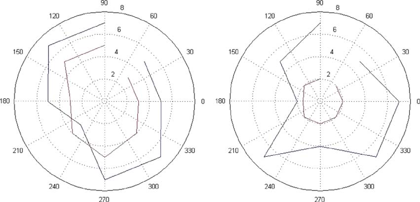
(Outer, blue) γ
valent of the FCC mask. The pulse is then upconverted to the de-
c and (inner, red) γr for (left) Hankook and (right)
Pirelli in nanoseconds.
sired carrier frequency with a carrier pulse. The benefit is that thepulse shapes are straightforward to generate without any specialfilters or hardware, and the center frequency is easy to control.
The triangular sinusoid is a better fit in the FCC mask and offersmore bandwidth in the main lobe of the frequency response.
Thus, the triangular sinusoidal pulse is the natural choice.
2) Modulation: Only binary-modulation schemes were ex-
plored for the Intelligent Tire system, since complex modu-lations would also increase power consumption due to morecomplex architectures. Specifically, pulse-amplitude modula-tion (PAM), on–off keying (OOK), pulse-position modulation
α for (left) Hankook and (right) Pirelli.
(PPM), and binary phase-shift keying (BPSK) are compared.
is due to the much shorter flight distances involved in the tire
In PAM and OOK, the "0" and "1" bits are represented by
area as compared to the scenarios considered in the standard.
analog signals of two distinct peak amplitudes. Specifically,
OOK only outputs a pulse for the "1" bit. The advantage is that
c and λr were found not to vary much in different positions.
Much greater variation was observed for cluster decaying factor
it is relatively straightforward to implement, without adding
and ray decaying factor, γ
any additional components to the transmitter. The disadvantage
c and γr , respectively. They are shown
is that if the difference between the amplitudes for the "0"
A very important system parameter that can be extracted
bit signal and the "1" bit signal is too small, then the signal
from the time-domain model is the delay spread. Delay spread
is extremely sensitive to channel noise and interference. In
is defined as the time at which the impulse response falls below
addition, in OOK, a "0" bit cannot be distinguished from the
the noise floor. In the measurements, the noise floor is very low,
lack of a signal at the receiver, making timing recovery and
and the delay spread is 20–30 ns, as shown, for example, in
synchronization more difficult.
Fig. 7. The final major parameter that was extracted was the
For PPM, information is conveyed via the position of a
channel attenuation, and it is designated as α, as shown in
pulse in the time domain with respect to a specific location.
Fig. 9. The values for the Pirelli tire are generally larger than
PPM is more robust to channel noise than most PAM systems.
for the Hankook tire. This is easily attributed to the thicker
The bit-detection process is simple; however, it requires care-
and more robust construction of the Pirelli tire. Following the
ful synchronization between the transmitter and the receiver,
determination of channel model, the UWB system is designed.
since the locations of the "0" and "1" bits are critical for
There are two broad categories of UWB systems: impulse
this modulation scheme. Luckily, UWB signals have a wide
radios (IRs) and multiband orthogonal frequency-division mul-
delay spread relative to its pulsewidth due to the abundance of
tiplexing (MB-OFDM) radios. IR systems directly generate
multipath components, which helps relax the synchronization
the UWB frequency spectrum via ultrashort pulses, whereas
requirements. However, synchronization must still be on the
MB-OFDM is an adaptation of traditional narrowband OFDM
order of tens of nanoseconds.
technology that forms an aggregate equivalent bandwidth of at
BPSK distinguishes between the "0" and "1" bits by the
least 500 MHz. We focus on IR, since the energy-constrained
phase of the signal. A major disadvantage to this scheme is
environment of the application is unable to handle the architec-
that an energy-detection approach is no longer possible for
tural complexity of the MB-OFDM systems.
bit detection, since both the "0" and "1" signal gives the
IEEE TRANSACTIONS ON COMPUTER-AIDED DESIGN OF INTEGRATED CIRCUITS AND SYSTEMS, VOL. 28, NO. 7, JULY 2009
UWB RECEIVER SCORECARD
UWB transmitter.
Energy detection at baseband receiver for UWB detection.
same energy. Instead, coherent receiver architectures, such asa matched-filter design, must be utilized to track the phase of
energy-detection at baseband was determined to be the best
the incoming signals, which complicates receiver architecture,
detection algorithm to be used as UWB receiver. UWB signals
particularly in the presence of an unpredictable channel.
have a very rich multipath profile, which makes correlation-
PPM turns out to be the best option for this application
based receivers unreliable to use. Although energy-detection
due to the simplicity allowed for the receiver architecture and
receivers are prone to interferences from other signals, we hope
robustness under severe in-band interference and multipath ef-
that the rich multipath profile of UWB signals will help to
fects. Compared to BPSK, PPM allows the use of noncoherent
mitigate this problem.
receiver architectures such as energy-detection receiver since
The architecture for the uplink receiver, shown in Fig. 11, is a
we do not need to track the phase of the incoming signals.
modification of the classical energy-detection receiver that first
Compared to PAM or OOK, PPM is more robust and inherently
downconverts the incoming signal band and performs energy
carries timing information from the sensor nodes allowing
detection. The incoming signal is first split into two paths and
better synchronization with the PAN coordinator.
downconverted in I and Q channels. The two signals are then
3) UWB Communication Architecture:
filtered to remove unwanted higher order signals. The resulting
Transmitter front end: The uplink radio needs to transmit
signals are squared and added to produce the final signal. This
at a fairly high data rate, greater than 1 Mb/s, and needs to
signal is an estimate of the power of the modulating signal that
consume as little power as possible in the transmitter. Thus,
is not sensitive to the phase of the incoming signal. The signal
we chose a simple transmitter architecture consisting of a ring
is finally integrated, and the output (aka chips) is sampled and
oscillator to generate the carrier signal and a pulse controller to
made available to the digital baseband section for detection.
generate the modulated baseband signal, as shown in Fig. 10.
Baseband processing: The packet structure and baseband
Receiver front end: Power constraints of the sensor nodes
processing of the system are based on, but not necessarily
allowed us very few options to play with for the transmitter. The
compliant with, IEEE 802.15.4a standard [13] and consist of
receiver on the PAN coordinator, however, was not subject to
the following processes.
such stringent constraints; thus, several architecture alternatives
1) Chip synchronization: Using the received preamble, finds
were feasible. Since the Intelligent Tire system had such asym-
the locations of the incoming pulses to synchronize the
metric design constraints, much of the burden for combating
analog front end in preparation for the incoming packet.
adverse channel effects have been shifted to the receiver side.
2) Despreader: Decodes the incoming chips into bits. In
The goal was to find a receiver architecture that had good
the Intelligent Tire system, an 8-b pseudonoise (PN)
enough sensitivity to capture the UWB signals in the presence
sequence spreading is used to combat channel effects.
of a harsh channel. In addition, the receiver needs to be robust to
3) Packet detection: Detects the beginning and end of a
in-band interference signals and maintain a relatively consistent
performance. A matched-filter type of design was out of the
question, since the short duration of UWB signal would place
Solomon (RS) coding scheme, and a half-rate convolution
tremendous burden on the analog-to-digital converters at over
encoder is used to reduce error.
10-GHz sampling frequency. Although the PAN coordinator
5) Cyclic-redundancy-check (CRC): Parity check for packet
is not as power constrained as the sensor nodes, it is still
limited. The choices that were evaluated were energy-detection
The transmitter baseband-processing chain contains the cor-
receivers at RF and baseband, and correlation receivers at RF
responding components, which are mapped onto a low-power
and baseband. Scorecard of each of the receiver architectures is
DSP. The main purpose of the digital baseband blocks in the
shown in Table I. Scores range from 1 to 5, where 5 is the most
transmitter is packet generation (Fig. 12). The packet structure
sensitive, and 1 is the least.
used is inspired by the structure specified in IEEE 802.15.4a
As expected, energy-detection-based receivers are more sen-
with a few modifications to suit our application. First, given M
sitive to SNR, whereas correlation-based receivers become very
information bits from the application, MAC packet is formed
unpredictable in the presence of multipath effects. Overall,
by adding MAC header including 1 B for sequence number
ERGEN et al.: TIRE AS AN INTELLIGENT SENSOR
CER SIMULATION RESULTS
Packet structure used for the application with respective number of
symbols (chips) for each field. We assume M = 32 B for the MAC simulations.
BER SIMULATION RESULTS
to detect packet losses and 2 B for destination and sourceaddress, and a CRC calculated over both the MAC header andthe data payload for packet validation. The method used was thecommon CRC-8 procedure. Next, following procedures in thestandard, the data are encoded for error correction. The forward
error-correction encoder consists of an inner RS encoder and an
IMULATION RESULTS
outer convolutional encoder. The RS encoder appends 48 paritybits to the MAC packet and feeds into a half-rate convolutionalencoder, which produces 2(M + 32 + 48) b. The RS encoderuses the following generator polynomial:
g(x) =
(x + ak)
= x8 + 55x7 + 61x6 + 37x5 + 48x4
+ 47x3 + 20x2 + 6x + 22.
Then, spreading is done by directly mapping each symbol to
PPM-modulated triangular-sinusoid UWB pulse transmissions
a constant PN sequence. This differs from the standard, which
in MATLAB (which takes about 90 min on an AMD Turion X2
employs a time-hopping spreading technique based on a time-
laptop). Under the assumption of 8-b pseudorandom spreading,
varying PN sequence. The change to direct PN spreading allows
the CER to bit-error-rate (BER) result is given in Table III. After
reduced complexity in the transmitter of the sensor nodes and
packet detection and ECC decoding, the BER to packet-error-
less stringent synchronization requirements for the receiver
rate (PER) result is given in Table IV. The PER information
will be used in the design of the communication protocol as
The preamble then consists of two fields: SYNC, responsible
a measure of the PHY layer performance. Specifically, we
for establishing clock synchronization and timing recovery, and
design a protocol, as will be discussed in Section VI, under the
the start field delimiter (SFD), responsible for denoting the
assumed PER of 5%, since channel measurements show that
beginning of an incoming packet to the receiver. Due to the
SNR is around 12 dB for the pulse duration.
time constraint of the transmission frame, we use the smallestpreamble size dictated by the standard, i.e., 16 SYNC symbols
B. Downlink Communication
and 8 SFD symbols, by default but the length can be adjustedby the PAN coordinator if needed. In addition, since the length
Downlink transmission from PAN coordinator to tire sensor
and the data rate of the packet for our application is fixed, we
nodes is used primarily to transmit minimal information for
eliminate the PHY header. The final packet structure used for
MAC scheduling, as detailed in Section VI. Due to the low-
the Intelligent Tire system is shown in Fig. 13. An additional
data-rate requirements, narrowband communication is used.
deviation from the standard's UWB PHY specifications is the
Furthermore, we apply an ultra-low-power radio design due
modulation scheme used. As mentioned in Section V-A-2, bi-
to power restrictions of the sensor nodes. The power of the
nary PPM (BPM) is used for this application to reduce receiver
downlink receiver needs to be under 100 μW. The only viable
complexity, whereas the standard uses BPM-BPSK modulation
architecture to demonstrate this low of a receiver power is
for each two symbols.
based on energy-detection [18]. Other radio receivers have
UWB simulation: Upon selecting the communication ar-
been demonstrated with system powers on the order of a few
chitecture, we need to extract the performance information of
hundred microwatts. The key to using less than 100 μW is the
the PHY layer into the MAC layer. Since physical implementa-
elimination of the local oscillator and the use of a low-power
tion is not yet complete, we can only evaluate at the functional
MEMS-based bulk-acoustic-wave (BAW) front-end filter. This
level. Specifically, the performance is reported in terms of chip-
influences most other decisions in the receiver design and yields
error rate (CER) in Table II. This is the lowest level of ab-
the basic architecture, as shown in Fig. 14. Its basic operation
straction for the radio before physical implementation. In-band
consists of determining whether RF energy exists in a given
interference for the channel was modeled as an additive white
frequency band. The signal is coded for interference mitigation.
Gaussian noise channel with appropriate SNR assignment. The
The operation of the receive chain is as follows. The in-
multipath profile for the channel is based on the channel model
coming signal is first filtered so that only the narrowband of
we developed. Each result is based on a simulation of 10 000
interest is admitted. The performance of this BAW filter is
IEEE TRANSACTIONS ON COMPUTER-AIDED DESIGN OF INTEGRATED CIRCUITS AND SYSTEMS, VOL. 28, NO. 7, JULY 2009
antenna and the narrowband antenna wrap around multiplesides of the cube, they will become entangled and affect eachother's fields. It is advantageous to design a single radiatingstructure that operates in two bands: the UWB band as wellas the ISM band for the narrowband radio. This requires morecomplex isolation circuitry, but should be possible, since thetwo radios will not operate at the same time, according to theMAC scheme presented in this paper.
Example antenna design.
VI. PROTOCOL DESIGN
crucial to the operation of the receiver, since any RF energythat is admitted by this filter is detected by the receiver. The
The MAC protocol manages medium contention between
MEMS technology also helps in reducing power consumption.
different sensor nodes. A well-designed MAC for wireless
The RF signal is then amplified by a low-noise amplifier, which
applications not only minimizes medium-access contention but
provides a modest gain (10–15 dB) while adding minimal noise.
also achieves this with minimal energy and delay overhead [24].
The signal is then demodulated by a nonlinear element. The
MAC protocols can be classified using four main categories:
resulting signal has power at baseband if there is energy at
random access, frequency-division multiple access (FDMA),
RF. The signal is then low-pass filtered to detect the energy
code-division multiple access (CDMA), and time-division mul-
at baseband. The energy is integrated and then digitized. OOK
tiple access (TDMA) [21]. Due to the relatively large amount
modulation is used, and bit detection uses a single threshold
of information bits that need to be transmitted within a limited
detector on the digitized input stream.
time window in the Intelligent Tire system, random-accessschemes, which takes time to assess channel conditions beforeeach transmission, are not suited. FDMA is not a solution,
C. Antenna Design
since the needed frequency programmability increases the com-
The node requires two antennas: one for the UWB uplink
plexity of the sensor nodes, which results in higher energy
radio and one for the narrowband downlink radio. Efficient
consumption and cost. CDMA is a viable choice; however, the
antennas are usually on the order of 1/2 of the wavelength
harsh channel conditions make intersymbol interference among
of interest in some physical dimension [25]. For example, the
the sensor nodes a concern. In addition, extra coding may be
length of thin-wire dipole antenna is 1/2 of the wavelength of
needed, which reduces the overall throughput of information
the center frequency. This presents a problem to the current
bits in the system. TDMA has several advantages for our
system, since the node is much smaller than the wavelengths
of interest. Furthermore, the antenna is not allowed to stick out
1) It allows nodes to transmit only during the allotted time
from the node, which means that the other parts of the node are
slot and sleep, otherwise, to save power.
part of the near field of the antenna. This could cause the field
2) During the assigned transmission time, the sensor node
pattern to change significantly as well as shifting the tuning
will not have to contend with any other sensor for channel
point of the antenna. The antenna is also restricted to the surface
access, reducing interference and delay.
of the node to avoid blocking the antenna's radiation, since
3) No extra circuitry is needed; thus, the energy overhead is
the interior of the node will be filled with other subsystems.
Moreover, the antenna location is very near metal mesh of thetire, which impacts performance. Note that all of these issues
On the other hand, TDMA does have shorter transmission
essentially relate to the physical size or extent of the antenna.
time per sensor node as compared with CDMA or FDMA;
There are various techniques to deal with the earlier issues.
however, since we only have a maximum of three sensor nodes
One way is to reduce the physical size required for a resonant
per tire, this will not present a major problem.
antenna by employing various miniaturization techniques [26]
Hence, TDMA seems to be the best choice. However, we
such as substrates with high dielectric constants and slow-wave
cannot use existing schemes [19], [20], which require either
structures. A related technique simply uses antennas that are
a long scheduling instructions from the PAN coordinator or
less than 1/2 the wavelength (possibly much less) which are not
some complex network-synchronization scheme. Due to power
themselves resonant. More complex matching techniques are
limitations, we cannot afford a standard RF receiver on the
then used to make these small nonresonant antennas radiate and
sensor node. Only limited information can be received via a
receive efficiently. The matching requirements tend to be sen-
wake-up radio. Therefore, we must control media access by
sitive to changes, including the near-field physical environment
sending as little information to the sensor nodes as possible.
for narrowband antennas. In the case of wideband antennas, the
In response to these considerations, we propose a new MAC
matching requirements can be quite difficult to achieve.
protocol, which applies to a special class of ultra-low-power
Some preliminary designs use more than one face of the node
data-acquisition wireless networks, where the sensor nodes are
by wrapping the antenna around two or even three sides of the
subject to stringent energy constraints.
cube (see Fig. 15 for example antenna design). This allows a
The proposed MAC scheme, called ISTD-MAC, is a TDMA
longer length for the antenna but is much more complex to
protocol that features implicit generation of a transmission
analyze, requiring numerical simulations. This has the potential
schedule using an ordered-priority scheme. Each node deter-
to exacerbate the proximity effects of the rest of the node on the
mines its own allocated time-slot based on very limited infor-
antenna, as well as from the other antenna. If both the UWB
mation sent by the PAN coordinator via the beacon packet.
ERGEN et al.: TIRE AS AN INTELLIGENT SENSOR
Tframe consists of n Tslot, where Tslot is the time allotted for a
single-sensor node to transmit data and n denotes the number of nodes in thesystem.
This implicit method simplifies node receiver architecture andenergy consumption.
Transmission schedule of ISTD-MAC for Intelligent Tire system.
Note that, while ISTD-MAC was expressly developed for
the Intelligent Tire system, it can be used in a fairly large set
fairness, internode interference, and delay overhead. We want
of power-limited WSN applications. For our application, three
to reduce delay overhead by assigning a large Tslot to re-
types of communication activity have to be managed: network
duce the number of guard intervals and to shrink the duration
initialization, data transmission, and retransmission.
of the guard intervals; however, we also need to make surethat the guard intervals are long enough to eliminate possiblepacket collisions between sensor nodes. In addition, we want
A. Network Initialization
to maintain a fairness of channel conditions for all the sensornodes by interleaving transmission such that no sensor node
Upon acquiring relevant data from the sensors, a master
transmits only during good channel conditions or vice versa.
node initializes network communication by sending a beacon-
Simulation shows that a T
request packet(s) to the PAN coordinator when the power
slot of ten packet transmissions with
10% guard interval works well for the Intelligent Tire system,
supply becomes sufficient. The master node repeatedly sends
but a more rigorous optimization might be needed to further
the beacon request packet(s) until a beacon packet is received
increase system throughput.
from the PAN coordinator. Based on the time arrival of the
The node waits T
beacon-request packet sent by the master node, the beacon
frame after each transmission slot before
transmitting again. This automatic-scheduling mechanism is
packet carries the following information:
the heart of our MAC scheme. Each node avoids having to
1) the total data-transmission time allocated for the net-
receive complex scheduling instructions explicitly from the
work Ttx0;
PAN coordinator. During the wait periods, the node processes
2) the time left for transmission Ttx;
data to prepare for the following transmission frame. Thus, the
3) the number of nodes that are currently in the network N .
nodes only perform one function at any given time, lowering
The beacon is transmitted periodically (every Tframe) until
the peak energy consumption. The transmission cycle continues
the PAN coordinator has received valid packets from all N
until either no more data are available to be sent or the current
nodes. With each beacon transmission, the beacon packet is
transmission interval has expired. If there are no data to transmit
updated with the information of how much more time is left for
during the allocated transmission slot, the node sends a keep-
the current transmission interval Ttx. In addition, the PAN coor-
alive packet to remain synchronized with the PAN coordinator
dinator also updates itself for when to generate the appropriate
and goes into sleep mode.
beacon for the next transmission interval. This information is
Fig. 17 shows an instance of the transmission schedule for
based on its knowledge of the transmission cycles, when the
the Intelligent Tire system. In this case, the beacon packet
initial beacon request from the master node was received, and
was initially missed by nodes 1 and 2; however, subsequent
possible additional system information.
transmissions were still operational without any medium-accessconflicts due to the implicitly generated schedule.
B. Data Transmission
Upon receiving the beacon packet, the node updates the
C. Retransmission
local Ttx, Ttx0, and N to implicitly generate the transmit
ISTD-MAC reduces the PER with a retransmission scheme.
schedule. Each node is associated with an order number ai,
During retransmission, the PAN coordinator begins to broadcast
ai ∈ {1, . . , N }. Based on ai and the beacon information, we
Rbeacon packets during the last 10% of the current transmission
can determine Twait initial and T
frame, which implicitly give us
cycle. Rbeacon contains the IDs of all the missing packets
the TDMA schedule of the network
from each node. During this time, the nodes also go into
listening phase. Upon receiving a complete Rbeacon packet, the
i ∗ Tslot
receiver is turned off. If no retransmission is needed, nodes
Tframe = N ∗ Tslot.
will go into sleep mode. Note that retransmission is explicitly
Fig. 16 shows the assumed time-slot structure. Each node
scheduled at the PAN, since we expect only a limited number
waits for Twait initial time until its allocated transmission slot.
of retransmissions needed. Thus, R
beacon packet will not be a
After the allotted transmission slot has expired, the node goes
burden for the downlink receiver. All transmission cease at the
back into wait mode to prepare for the next transmission slot.
end of Ttx0.
A guard time of 0.1 Tslot is used between sensor nodes to avoid
Fig. 18 shows an instance of the retransmission scheme. Note
possible interferences due to clock mismatches. The assignment
that if the sensor node misses the Rbeacon packet, then the PAN
of Tslot and guard time is a tradeoff between transmission
coordinator continues to request the missing packets at the next
IEEE TRANSACTIONS ON COMPUTER-AIDED DESIGN OF INTEGRATED CIRCUITS AND SYSTEMS, VOL. 28, NO. 7, JULY 2009
System PER versus nominal PER plot from MAC simulations.
MAC CFSM model.
retransmission frame, as long as the total transmission time T
MAC energy profile for nodes 1, 2, and 3.
has not expired.
Fig. 21 shows the energy profile of the sensor nodes at
different intervals of operation. With the exception of network
D. MAC Analysis
initialization in the master node, energy consumption is kept
To verify the functionality of ISTD-MAC, we created, in
below 175 nJ per packet time (320 μs) at any given time.
Simulink, a codesign finite-state machine (CFSM) [17], which
This is roughly 55% of the total power available, assuming a
is a globally asynchronous–locally synchronous model of com-
1-mW power source. The rest the energy can be stored for other
putation. As shown in Fig. 19, the sensor nodes and PAN
operations of the sensor node. Although the energy profiles are
coordinator are modeled as FSMs, each synchronized to a local
based on preliminary energy estimation, we can infer that the
clock. Operations in sensor nodes are annotated with estimated
MAC protocol spreads the sensor operation through time so that
energy-consumption figures. To simulate real operation con-
the peak power consumption is kept low. Thus, ISTD-MAC is
ditions, the communication between sensor nodes and PAN
able to virtually eliminate medium contention while still staying
coordinator is modeled as an asynchronous process. Taking
within the assumed energy budget of 1 mW.
input from the triggering algorithm, as well as extracted PHYlayer nonidealities such as PER, clock jitter, and clock skew,
VII. DESIGN-SPACE-EXPLORATION STRATEGY
the MAC model generates a stream of received packets forvalidation of the protocol and an energy profile for each of the
As discussed previously, the design of the Intelligent Tire
sensor nodes.
system requires expertise in multiple engineering disciplines,
Fig. 20 shows the PER performance of the system (i.e.,
including integrated-circuit design, communications, signal
cumulative for all three sensors), with and without packet
processing, real-time software design, antenna design, energy
retransmission as a function of single-sensor PER. The sim-
scavenging, and system assembly. In addition, the harsh operat-
ulation setup assumed 1-Mb/s data rate, 40-B packet size,
ing conditions require aggressive design-space exploration, not
10 packet transmissions per allocated time slot per sensor,
only for each individual component but also for the system as a
18 full wheel rotations with varying velocities, and triggering
whole. The design methodology we adopted is platform-based
data from actual sensor data. Without retransmission, the PER
design (PBD) [27]. The methodology is a meet-in-the-middle
of the overall system is roughly the same as the nominal
process that allows for systematic design-space exploration,
single-sensor PER. No additional packet errors were added
where successive refinements of the application specifications
to the system; therefore, we can conclude that no medium
meet various abstractions of potential implementations. The
contentions (i.e., packet collisions) between the sensor nodes
orthogonalization of concerns is key to PBD. By separat-
occurred. With retransmission, the system PER dropped to well
ing application functionality from architecture implementation,
below 1%, with a maximum PER reduction of 95%, simply by
PBD can be utilized to design very complex heterogeneous
allocating 10% of the transmission window for retransmission.
ERGEN et al.: TIRE AS AN INTELLIGENT SENSOR
automotive-safety applications. The wireless sensor network isbased on sensor nodes placed inside each tire of an automobilethat measure a number of important values to diagnose andcontrol stability and traction. The design of an IntelligentTire system requires expertise in multiple engineering dis-ciplines including integrated-circuit design, communications,signal processing, real-time software design, antenna design,energy scavenging, and system assembly. In addition, the strictrequirements in terms of energy consumption, data rate, delay,and reliability require aggressive design-space exploration, notonly for each individual component but also for the system asa whole. A PBD approach was used to deal with the designcomplexities of this challenging system.
PBD for Intelligent Tire system.
In summary, we first mapped the application onto a set of
algorithms, which determines the required resolution and rate
Currently, there are no commercial PBD-based toolset that
of the signal acquisition, and delay and reliability requirements
can deal with such a heterogeneous system as the Intelligent
for the communication network. We then determined the best
Tires; however, PBD is still the core strategy used in design-
energy source to be batteryless technology based on either
space exploration of this paper. Fig. 22 shows how PBD is
energy scavenging or on external power delivery via an RF link.
applied to the Intelligent Tire system. First, we separate the
These constraints are then used in mapping the system function-
required functionality of the system from the available en-
ality to hardware architecture. The severe multipath environ-
ergy resources. Note that, although energy resources and the
ment of the tire and extreme energy constraints resulted in the
signal-processing algorithms were decoupled, decisions made
choice of impulse-based UWB transmitter and energy-detection
on the energy platform still impact which implementations
receiver at the tire sensor nodes. The issues and tradeoffs in
are feasible for the application. Thus, an order is needed for
choosing transmitter and receiver architectures were discussed.
design-space exploration. Specifically, we first narrow down the
Moreover, the energy constraints when combined with delay
energy resources that suit our application to provide an energy
and reliability requirements of the application resulted in a new
budget. This result is then used as a constraint as we map the
TDMA-based MAC protocol design.
system functionality to hardware architecture. The next step in
Several experimental tests have been carried out in Vizzola
exploration is to map the application onto a set of algorithms,
Ticino Pirelli Track by using different tires at different speeds,
which directly constrain the type of signal acquisition and
different tracks, and different sensor positioning. The measure-
communication networks needed for the system. We should
ments show that, depending on the parameter and the relating
also note here that even though the communication and data-
algorithm involved, a resolution in the range of 11–16 b and a
acquisition functionalities of the system can be represented at
maximum sampling frequency of 10 kHz for each channel is
the same level of abstraction using, for example, a data-flow
needed to get useful information. In the present configuration,
model, we still orthogonalize the problem to reduce complexity
the sensor node may choose to either transmit raw data to the
at lower levels of exploration. The intricacies of the wireless-
onvehicle PAN coordinator, where postprocessing is carried out
communication problem require more levels of abstraction for
to obtain final control quantities such as friction and slip angle,
efficient design-space exploration, such as the MAC and the
or to process the data directly and transmit the final control
PHY layers of the OSI model, whereas the data-acquisition
quantities to the PAN coordinator at a lower data rate. A correct
network can be mapped directly to the circuit platform for phys-
tradeoff between the amount of processing and transmission
ical implementation. The interaction between the MAC and the
of sensor nodes depends on the complexity of the algorithms,
PHY layers were already mentioned in Sections V and VI. At
the capability of microprocessor on the sensor nodes, and the
each level of abstraction, as shown in Fig. 22, we must map
required parameters from other electronic control units in the
the propagated constraints onto a set of components that repre-
vehicle such as steering angle and speed.
sent performance abstractions of lower level implementations.
We are presently working toward a fully working prototype
Due to the lack of PBD-compliant tools, as well as available
of the system, and we are researching innovative applications
libraries, for such a novel application as Intelligent Tires, the
that utilize the underlying technology. To aid in realizing the
mapping process has mostly been manual and simulation based.
prototype, we will focus our design methodology on mixed-
However, the experiences gained, as well as the models built,
signal systems. We will focus on populating the general PBD
will be instrumental in perfecting our methodology and toolset
framework with a set of tools and methods to support the
for second-generation implementations of this application or
following features:
similar ultra-low-power sensor-network applications. In addi-tion to implementation, automatic mapping of data-acquisition
1) efficient and accurate modeling of circuit (RF, analog,
and communication schemes onto hardware implementation is
digital, and mixed signal) performance space to create a
currently being explored.
comprehensive component library to serve as a platformfor high-level system design;
2) automatic physical architecture synthesis (component
VIII. CONCLUSION AND FUTURE WORK
composition) of mixed-signal systems given application-
We presented the architecture and the considerations that
specific signal-processing algorithms and the component
were used to design a complex wireless sensor network for
library to generate the set of all feasible architectures;
IEEE TRANSACTIONS ON COMPUTER-AIDED DESIGN OF INTEGRATED CIRCUITS AND SYSTEMS, VOL. 28, NO. 7, JULY 2009
3) global (architecture and circuit configuration) system op-
[26] P. Bhartia, I. Bahl, R. Garg, and A. Ittipiboon, Microstrip Antenna Design
timization to determine optimal system design for the
Handbook. Norwood, MA: Artech House, 2000.
[27] A. Sangiovanni-Vincentelli, L. Carloni, F. D. Bernardinis, and M. Sgroi,
given application.
"Benefits and challenges for platform-based design," in Proc. 41st Annu.
These tools and methods will help in determining to best
DAC, 2004, pp. 409–414.
mapping of the Intelligent Tire system's signal acquisition and
[28] S. Roundy, M. Strasser, and P. K. Wright, Powering Ambient Intelligent
Networks. Berlin, Germany: Springer-Verlag, Dec. 2005, pp. 271–299.
communication functionalities onto the set of available circuitcomponents to minimize overall system cost.
Sinem Coleri Ergen (S'98–M'07) received the B.S.
degree in electrical and electronics engineering from
[1] T. Schrüllkamp, H. Goertz, and T. Hüsemann, "Development of an intelli-
Bilkent University, Ankara, Turkey, in 2000 and the
gent tire—Experiences from the APOLLO project," in Intell. Tire Technol.
M.S. and Ph.D. degrees in electrical engineering and
Conf., Frankfurt, Germany, Nov. 2005.
computer sciences from the University of California,
[2] J. Yi, "A piezo-sensor-based ‘smart tire' system for mobile robots and
vehicles," IEEE/ASME Trans. Mechatronics, vol. 13, no. 1, pp. 95–103,
Berkeley, Berkeley, in 2002 and 2005, respectively.
Since July 2006, she has been a Research Sci-
[3] A. Todoroki, S. Miyatani, and Y. Shimamura, "Wireless strain monitoring
entist with the Wireless Sensor Networks Berkeley
using electrical capacitance change of tire with oscillating circuit," Smart
Laboratory, Berkeley, which is under the sponsorship
Mater. Struct., vol. 12, no. 3, pp. 403–409, Jun. 2003.
of Pirelli and Telecom Italia. Her research interests
[4] N. Robinson, III and J. H. Matthews, "Remote tire pressure monitoring
include wireless communications and networking,
system employing coded tire identification and radio frequency transmis-
collaborative signal processing, and embedded systems.
sion and enabling recalibration upon tire rotation or replacement," Patent:
Dr. Ergen was the recipient of the Regents Fellowship from the University of
5 838 229, Nov. 17, 1998.
California, Berkeley, in 2000, and the Bilkent University Full Scholarship from
[5] K. E. Mattson, L. W. Hamm, W. K. Cotton, R. A. Stewart, M. A. Uleski,
Bilkent University in 1995.
R. B. Belden, and M. A. Peterson, "Tire pressure monitor system withside entry pressure port," Patent: 7 377 156, May 27, 2008.
[6] J. P. Robillard, B. S. Honeck, J. R. Geschke, and M. J. Suman, "Tire
monitoring system," Patent: 6 259 361, Jul. 10, 2001.
Alberto Sangiovanni-Vincentelli (F'82) received
[7] R. Behringer and N. Muller, "Autonomous road vehicle guidance from
the "Dottore in Ingegneria" degree (summa cum
autobahnen to narrow curves," IEEE Trans. Robot. Autom., vol. 14, no. 5,
laude) in electrical engineering and computer sci-
pp. 810–815, Oct. 1998.
ence from the Politecnico di Milano, Milano, Italy,
[8] A. Nepote, P. Pierre, T. Varpula, A. Rautiainen, and K. Jaakkola, "The in-
telligent tire: Acceleration sensors data acquisition," in SAE World Congr.,
From 1980 to 1981, he was a Visiting Scientist
Apr. 2005, pp. 59–66.
in the Mathematical Sciences Department, IBM T. J.
[9] World Health Organization, World Report on Road Traffic Injury
Watson Research Center, Yorktown Heights, NY. In
1987, he was a Visiting Professor at Massachusetts
[10] S. Muller, M. Uchanski, and K. Hedrick, "Estimation of the maximum
Institute of Technology, Cambridge. He has held
tire–road friction coefficient," Trans. ASME, J. Dyn. Syst. Meas. Control,
a number of Visiting Professor positions at Italian
vol. 125, no. 4, pp. 607–617, Dec. 2003.
Universities, including Politecnico di Torino, Torino, Italy; Universita' di
[11] F. Gustafsson, "Slip-based tire–road friction estimation," Automatica,
Roma, La Sapienza, Rome, Italy; Universita' di Roma, Tor Vergata, Rome;
vol. 33, no. 6, pp. 1087–1099, Jun. 1997.
Universita' di Pavia, Pavia, Italy; and Universita' di Pisa, Scuola di Sant'Anna,
[12] A. F. Molisch, K. Balakrishnan, D. Cassioli, C.-C. Chong, S. Emami,
Pisa, Italy. He was a cofounder of Cadence and Synopsys, the two leading
A. Fort, J. Karedal, J. Kunisch, H. Schantz, and K. Siwiak, "A com-
companies in the area of electronic design automation. He is currently the
prehensive model for ultrawideband propagation channels," in IEEE
Chief Technology Adviser of Cadence. He is a member of the Board of
GLOBECOM, Nov. 2005, vol. 6, pp. 3648–3653.
Directors of Cadence and the Chair of its Technology Committee, UPEK,
[13] IEEE 802.15.TG4a Official Web Page. [Online]. Available: http://www.
a company he helped spinning off from ST Microelectronics, Sonics, and
Accent, an ST Microelectronics–Cadence joint venture he helped founding.
[14] H. Sheng, P. Orlik, A. Haimovich, L. C. Cimini, Jr., and J. Zhang, "On
He was a member of the HP Strategic Technology Advisory Board. He is
the spectral and power requirements for ultra-wideband transmission," in
currently a member of the Science and Technology Advisory Board of General
IEEE Int. Conf. Commun, 2003, pp. 738–742.
Motors and of the Scientific Council of the Tronchetti Provera Foundation
[15] V. Somayazulu, J. R. Forester, and S. Roy, "Design challenges for very
high data rate UWB systems," in Conf. Rec. 36th Asilomar Conf. Signals,
and of the Snaidero Foundation. He is currently the Edgar L. and Harold
Syst., Comput., Nov. 2002, vol. 1, pp. 717–721.
H. Buttner Chair of Electrical Engineering and Computer Sciences with the
[16] X. Shen, M. Guizani, R. Qiu, and T. Le-Ngoc, Ultra-Wideband Wireless
Department of Electrical Engineering and Computer Science, University of
Communications and Networks. Hoboken, NJ: Wiley, 2006.
California, Berkeley, Berkeley, where he has been on the faculty since 1976.
[17] F. Balarin, H. Hseih, A. Jurecska, L. Lavagno, and A. Sangiovanni-
He consulted for many companies including Bell Laboratories, IBM, Intel,
Vincentelli, "Formal verification of embedded systems based on CFSM
United Technologies Corporation, COMAU, Magneti Marelli, Pirelli, BMW,
networks," in Proc. 33rd Annu. Conf. Des. Autom., 1996, pp. 568–571.
Daimler–Chrysler, Fujitsu, Kawasaki Steel, Sony, ST, United Technologies
[18] N. Pletcher, S. Gambini, and J. Rabaey, "A 65 uW, 1.9 GHz RF to digital
Corporation, and Hitachi. He was an Advisor to the Singapore Government
baseband wakeup receiver for wireless sensor nodes," in Proc. Custom
for microelectronics and new ventures. He consulted for Greylock Ventures
Integr. Circuits Conf., San Jose, CA, Sep. 2007, pp. 539–542.
and for Vertex Investment Venture Capital funds. He is a member of the
[19] D. Networks, Technical Overview of Time Synchronized Mesh Protocol
Advisory Board of Walden International, Sofinnova, and Innogest Venture
(TSMP), Jun. 2006. document number: 025-0003-01.
Capital Funds and a member of the Investment Committee of a novel VC Fund,
[20] S. Coleri and P. Varaiya, "PEDAMACS: Power efficient and delay
Atlante Ventures, by Banca Intesa/San Paolo. He is the founder and Scientific
aware medium access protocol for sensor networks," IEEE Trans. Mobile
Director of the Project on Advanced Research on Architectures and Design
Comput., vol. 5, no. 7, pp. 920–930, Jul. 2006.
of Electronic Systems, a European Group of Economic Interest supported by
[21] J. G. Proakis, Digital Communications, 4th ed. New York: McGraw-
Cadence, Magneti–Marelli, and ST Microelectronics. He is a member of the
Advisory Board of the Lester Center for Innovation of the Haas School of
[22] A. Goldsmith, Wireless Communications. Cambridge, U.K.: Cambridge
Business and of the Center for Western European Studies and is a member
Univ. Press, 2005.
of the Berkeley Roundtable of the International Economy. He is a member of
[23] A. V. Oppenheim and R. W. Schafer, Discrete-Time Signal Processing.
the High-Level Group, of the Steering Committee, of the Governing Board,
Englewood Cliffs, NJ: Prentice-Hall, 1999.
and of the Public Authorities Board of the EU Artemis Joint Technology
[24] M. G. D. Benedetto and G. Giancola, Understanding Ultra Wide Band
Initiative. He is a member of the Scientific Council of the Italian National
Radio Fundamentals. Englewood Cliffs, NJ: Prentice-Hall, 2004.
Science Foundation. He is an author of over 800 papers, 15 books, and 3 patents
[25] C. Balanis, Antenna Theory: Analysis and Design, 3rd ed. Hoboken, NJ:
in the area of design tools and methodologies, large-scale systems, embedded
Wiley, 2005.
systems, hybrid systems, and innovation.
ERGEN et al.: TIRE AS AN INTELLIGENT SENSOR
Prof. Sangiovanni-Vincentelli was the recipient of the Distinguished Teach-
Sayf Alalusi received the B.S., M.S., and Ph.D. degrees from the University of
ing Award of the University of California in 1981. He was also the recipient
California, Berkeley, in 1998, 2001, and 2005, respectively.
of the worldwide 1995 Graduate Teaching Award of the IEEE (a Technical
He first worked for HRL Laboratories Malibu, CA, on many diverse research
Field Award for "inspirational teaching of graduate students"). In 2002, he
tasks. He then joined the Wireless Sensor Networks Berkeley Laboratory,
was the recipient of the Aristotle Award of the Semiconductor Research
Berkeley, where he worked on low-power radios and wireless energy transfer
Corporation. He was the recipient of numerous research awards, including
projects for Pirelli's Smart Tire initiative. He is currently with TransRobotics,
the Guillemin–Cauer Award (1982–1983), the Darlington Award (1987–1988)
an early-stage start-up company in the San Francisco Bay Area, Hayward, CA,
of the IEEE for the best paper bridging theory and applications, and two
specializing in industrial sensing and automation.
awards for the best paper published in the IEEE TRANSACTIONS ON CIRCUITSAND SYSTEMS and IEEE TRANSACTIONS ON COMPUTER-AIDED DESIGNOF INTEGRATED CIRCUITS AND SYSTEMS. He was also the recipient of fivebest paper awards and one best presentation awards at the Design AutomationConference and other best paper awards at the Real-Time Systems Symposium
Giorgio Audisio received the degree in electrical
and the VLSI Conference. In 2001, he was the recipient of the Kaufman Award
engineering from the Politecnico di Torino, Torino,
of the Electronic Design Automation Council for "pioneering contributions to
Italy, in 1985.
EDA." In 2008, he was the recipient of the IEEE/RSE Wolfson James Clerk
He started his professional career with the Tele-
Maxwell Medal "for groundbreaking contributions that have had an exceptional
com Research Institute. In 1987, he joined Fiat
impact on the development of electronics and electrical engineering or related
Auto, where he was appointed Head of the Electrical
fields" with the following citation: "For pioneering innovation and leadership in
and Electronic Design Centre in 1997. During these
electronic design automation that have enabled the design of modern electronics
years, his team redesigned all the electrical and elec-
systems and their industrial implementation." He is a member of the National
tronic architectures of Fiat, Alfa, and Lancia models
Academy of Engineering, which is the highest honor bestowed upon a U.S.
with a dramatic improvement of reliability and cost
Engineer, since 1998.
reduction. After a period as Director of Innovation,
he was appointed as Deputy Director of the Electrical and Electronic Compe-tence Area, where he led the joint project with Microsoft for the development
Xuening Sun (M'02) received the B.S.E.E. degree
of a new telematics platform (Blue&Me) which is now deployed in all Fiat
(with highest honors) from the University of Texas
Auto and Iveco vehicles. In 2005, he joined Pirelli Tyres S.p.A., Milano, Italy,
at Austin, Austin, in 2004 and the M.S. degree from
as Chief Engineer of the Tyre Systems and Vehicle Dynamics Department to
the University of California, Berkeley, Berkeley, in
lead strategic development projects to transform the tire into an active and
2007, where he is currently working toward the Ph.D.
"intelligent" tire ("Cyber Tyre").
degree in the Department of Electrical Engineeringand Computer Science.
In 2005, he was with IBM, Austin, where he was
a Design Engineer for the zSeries server processorfamily before pursuing graduate studies in electronic
Marco Sabatini received the Laurea degree (with
design automation. In the summers of 2006 and
honors) in electrical engineering from the Politec-
2007, he was a Research Intern at the Pirelli/Telecom Italia Wireless Sensor
nico di Milano, Milano, Italy, in 1991.
Networks Laboratory, Berkeley, where he was involved in ultrawideband
He was with ST Microelectronics Central R&D,
system modeling and MAC protocol design. His research interests include
Agrate, Italy, where he worked on innovative HW
electronic-system-level design methodologies, with a special interest in system-
architecture design. In 1996, he was invited as
level composition of analog/RF circuits.
Visiting Industrial Fellow at the University ofCalifornia, Berkeley, Berkeley, where he workedon low-power analog-to-digital converter. In 1997,he joined ST Berkeley Laboratories, where he de-
Riccardo Tebano received the Laurea degree in
veloped advanced CMOS camera and solid state
physics from the Università degli Studi di Milano,
fingerprint-sensor technologies. In 2001, he was appointed as Vice President
Milano, Italy, in 1998 and the Ph.D. degree from the
of Engineering at Barcelona Design, where he was working on automatic
Università degli Studi di Milano-Bicocca, Milano,
synthesis of analog-circuit topologies. In 2004, he returns to Italy and worked at
Accent S.r.l. in the design and consulting service in the wireless-sensor field. In
He is currently with the Tyre System and Vehicle
2008, he joined Pirelli Tyres S.p.A., Milano, where he is currently responsible
Dynamics Department, Pirelli Tyre S.p.A., Milano,
for technologies for the "Cyber Tyre" project. He has published more than
17 patents and 7 papers at International Electron Devices Meeting, InternationalSolid State Circuits Conference (ISSCC), and other conferences. He was alsoassigned an "Exceptional Patent Award" by ST Microelectronics in 2000.
Source: http://wnl.ku.edu.tr/uploads/1/0/5/9/10590997/intelligenttire_cad2009.pdf
A GLOBAL PROBLEM! NOT JUST A CHINESE ONE! GlaxoSmithKline China executives face bribery probe Ministry says executives at China subsidiary of GlaxoSmithKline paid hospitals, doctors and influential groups to prescribe their brands of medication. Friday, 12 July, 2013. China's police say employees of drug manufacturer GlaxoSmithKline bribed doctors and hospitals to
Archives of Biochemistry and Biophysics 539 (2013) 9–19 Contents lists available at ScienceDirect Archives of Biochemistry and Biophysics Acetylsalicylic acid (aspirin) and salicylic acid interaction with thehuman erythrocyte membrane bilayer induce in vitro changes inthe morphology of erythrocytes Mario Suwalsky a,⇑, Jessica Belmar a, Fernando Villena b, María José Gallardo c,Malgorzata Jemiola-Rzeminska d, Kazimierz Strzalka d